Soft Maximum vs Hard Maximum

The other day i stumbled on an interesting concept called a “Soft Maximum”.

If you think of the normal maximum, you might have something like this:

float maxValue = max(valueA, valueB);

if valueA and valueB come from functions, there’s usually going to be a sharp bend in the graph of the above where the maximum value changes from valueA to valueB or vice versa.

Sometimes, instead of a sharp bend, you would like a smooth transition between the two values – like when using this for graphics or advanced mathematics.

Here’s the formula for soft max:

double SoftMaximum(double x, double y)
{
	double maximum = max(x, y);
	double minimum = min(x, y);
	return maximum + log( 1.0 + exp(minimum - maximum) );
}

Here are 2 really interesting links on computing and using soft max:

Soft Maximum

How to Compute the Soft Maximum

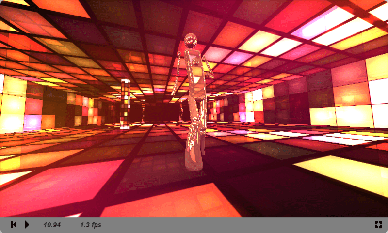
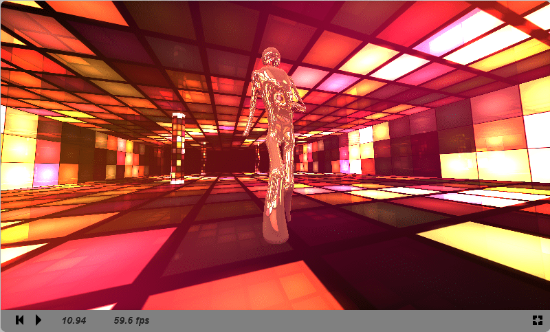
Check out the images below for an example of when you might use this. This is from a shadertoy shader The Popular Shader. The first image is with using normal max, and the second image uses soft max.

softminOFF

softminON

Converting RGB to Grayscale

If you were converting an RGB pixel to grayscale, you might be like me and be tempted to just add the red, green and blue components together and divide by 3 to get the grayscale equivalent of the color.

That’s close, but not quite correct!

Red, green and blue are not equal brightness, so doing a straight average gives you biased results.

There’s a wikipedia page on this topic here, but the equation to use is below:
grayScale = red * 0.3f + green * 0.59f + blue * 0.11f;

Here are some sample images to show you the difference.

Color:
color

Average:
avg

Weighted Average Equation:
good

Why?

You might be wondering “why the heck would i want to convert RGB to grayscale?”

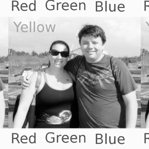
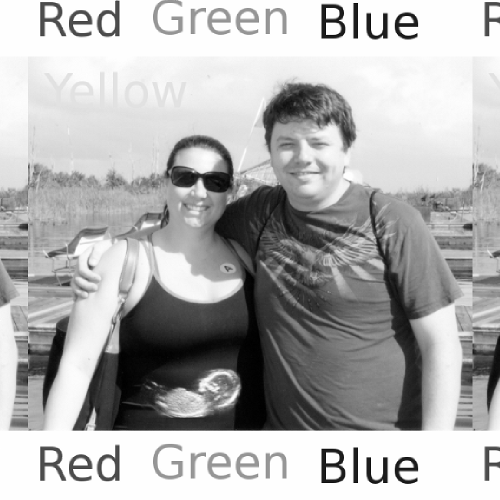
Well… if you render a scene once, convert it to grayscale and shove it into the red channel, then render the scene again slightly offset to the side, convert that to grayscale and shove it into the blue channel, you can get some neat images like the below. Red/Blue 3d glasses required, click the images to view the full size versions (;

Getting Ideal Disk Reads on the Cheap

If you are making a game, chances are you are loading assets and/or data from disk, and that you would like to load it in as fast as possible, so that players can play your game instead of staring at loading screens.

To make the fastest load possible, you want as few disk reads as you can get away with, you want them to be as large reads as possible, you want to read in the same order as the data is on disk, and if possible, you want to read from a single file that is kept open the whole time.

There are many reasons for why the above makes for ideal disk reading, but some of them are…

  • Every time you do a disk read, if the disk is in use by another process, you have to wait for that process to be done with the disk before you can start your read. The fewer disk reads you do, the fewer times you possibly have to wait on something else to relinquish the disk. Doing as large reads as possible makes for fewer disk reads too.
  • You want to read the data from disk in the same order that it’s stored on disk, because for some drive types (such as CDROM, DVD and hard disk drives) there is a physical “read head” that the drive has to move around to get to the data. The more that drive head has to move around, the longer you spend waiting for it to move, versus getting the data you want from the disk drive. Some drives, such as SSDs, have a zero seek time, but reading sequentially can also help out due to more efficient use of disk buffers.
  • You want to read the data from a single file when possible, versus having multiple files, because opening a file is expensive, and doing multiple reads from multiple files has a lot more erratic performance than doing multiple reads from a single file. Also, due to the fact that we usually have no way of knowing how files are actually laid out on disk, putting all the data into a single file is the only way to be sure that you can read data in order to minimize read head movements between reads (when the file is not fragmented on disk).

From Non Ideal to Ideal Disk Reads

So, how do you go from having a bunch of small reads from many different files, to fewer (or just 1) read from a single file?

Professionally made video games (especially console games) often will come up with a “packing process” to put all the files together into a single bundle, and possibly compress or encrypt it. Also, they’ll use this “pack time” opportunity to pre-calculate whatever they can that might be expensive at load time. For instance creating a Navigation Mesh or baking Lightmaps.

That is pretty cool, but is quite a bit of work. What if you don’t have the opportunity or willingness to make such a thing, or you want to get a sense of how much something like that would improve things?

Well, Paul, a buddy of mine, told me about a neat technique for doing this quickly and easily that after having heard it, I see references to ALL THE TIME now. It’s bizarre.

Basically, what you do is give your file read functions a special mode of operation where whenever they read data from disk, they also append that data to a special file.

After the load process is complete, you will then have a file that contains all the data your game wanted to read from disk during loading, in the order that it asked for it.

Next, you give your read and seek functions a special mode of operation where read will read from that special file, and seek will do nothing. You can open that file at the beginning of the load operation and close it at the end.

Following that, you are now a lot closer to ideal… you are reading from a single file, and you are reading sequentially.

For the rest of it (reading as few times as possible / doing as large reads as you can), if you have the RAM free, instead of having your disk read function read from the file, you could actually just load the whole file into RAM at once when loading starts (with a single disk read), and have your read function just serve data from memory. When loading is finished, you can free that memory from RAM, OR if you want to make subsequent loads faster (like if your game can have multiple plays in one session), you can keep it in memory so that the subsequent loads don’t even have to touch the disk drive.

Of course this assumes you have a deterministic read order, or that you can make it deterministic, etc etc, but it’s a pretty useful tool for the toolbox IMO.

Windows Does This Too!

Ok so as it turns out, the windows file cache (SuperFetch) uses a variation of this technique as well. Check it out!

From SuperFetch: How it Works & Myths

Let’s focus on decreasing boot times first. During the Windows boot process, the same files need to be accessed at different times. SuperFetch records which data and files need to be accessed at which times, and stores this data in a trace file. During subsequent boots, this information is used to make the loading of said data/files more efficient, resulting in shorter boot times.

SuperFetch performs more tasks to make the boot process more efficient. It also interacts with the defragmenter to make sure that the files accessed during the boot process are stored on the disk in the order they are accessed in. It performs this as a routine task every three days; the specific file layout is stored in /Windows/Prefetch/Layout.ini.

Transformation Matrix Basics

Here are some interesting tidbits of info that I’ve found useful for being able to think about matrix math in a more intuitive way. We start off with 2d matrix math but extend it to 3d at the end.

Why Use A Matrix?

You might ask why you might go through all the trouble of using a matrix for doing transformations like translation, rotation, scaling and shearing / skewing.

Why not just manually modify the points, putting them through equations to get the results. Well, there are two main reasons.

The first one is for performance. The function for rotating a point in 2d looks like this:

x’ = x * cos(theta) – y * sin(theta)
y’ = x * sin(theta) + y * cos(theta)

If you have 1000 points, that means you are calculating sin twice and cos twice for each point which is 4000 trig operations. If you are smart (or your compiler is!), you’ll only do sin and cos once for each point, but that’s still 2000 trig operations.

If you are super duper smart (or your compiler is…), you’ll notice that theta is the same for all 1000 points, and perhaps you’ll calculate sin(theta) and cos(theta) once ahead of time and use those values for each point.

That last step is basically what matrix math does for you. A 2d rotation matrix looks like the below:

[ cos(theta), sin(theta) ]
[-sin(theta), cos(theta) ]

That means that once you have calculated your rotation matrix, you don’t need to keep performing trig operations. You have your values and can use them over and over very cheaply.

This especially saves processor time when you combine multiple transformations together. If you needed to perform an operation that did some crazy combination of 2000 rotations, 2000 translations and 2000 scale adjustments, instead of needing to do those 6000 operations on each point, you can just calculate the final matrix (by combining the matrix of each of those 6000 operations into one matrix) and then use that single matrix to your hearts content.

Another reason why you might want to use matrices instead of doing transforms by hand is that it’s a lot simpler writing code that does general transformations instead of deciding after the fact “hey i want to add scaling now and i need to touch all my transformation related code to implement it”.

Using a matrix, you don’t have to know or care what the transform is, it will just do it and you can move on with your life.

Matrix Vector Multiplication Is Just Dot Products!

As a quick refresher, in 2d, a dot product is just 2 multiplies and an add (A.X * B.X + A.Y * B.Y) and in 3d, a dot product is just 3 multiplies and 2 adds (A.X * B.X + A.Y * B.Y + A.Z * B.Z).

A lot of modern hardware (both CPU and GPU) has varying amounts of support built in for vector and matrix math to make it faster, but matrix vs vector multiplies are really not that bad to begin with. In 2d, a matrix * vector operation is just 2 dot products! In 3d, it’s 3 dot products. Look at the below to see what I mean:

[VX VY]
*
[AX AY]
[BX BY]
=
VX’ = AX * VX + BX * VY
VY’ = AY * VX + BY * VY

and in 3d:

[VX VY VZ]
*
[AX AY AZ]
[BX BY BZ]
[CX CY CZ]
=
VX’ = AX * VX + BX * VY + CX * VZ
VY’ = AY * VX + BY * VY + CY * VZ
VZ’ = AZ * VX + BZ * VY + CZ * VZ

You Can Make a Matrix From Basis Vectors

Let’s say that you are working in 2d and you want to rotate a point. Let’s say that for some reason you know what the rotated X and Y axis are supposed to be. You can actually create a rotation matrix from that knowledge alone without having to do any trig or geometry type math.

Like for instance, if you wanted an object’s x axis to point parallel to the vector of a moving object, and you knew the object’s normalized velocity vector (the direction it is moving, normalized to have a vector length of 1) was (0.34, 0.93).

That normalized velocity vector would be your X axis, and you could use the “faked 2d cross product” of flipping x and y and negating one to get a vector perpendicular to that X axis (aka your Y axis) . So…

X axis = ( 0.34, 0.93)
Y axis = (-0.93, 0.34)

(note, which one you negate on the Y axis matters only as much as you care which of the 2 directions you want the Y axis to point. Basically if you don’t care if it points up or down, it doesn’t matter which one you flip. If you do care, you need to pick the right one for the direction you want. This may not be the best way, but i do it by visual inspection, or by evaluating the math and seeing if it’s pointing in the way that i want or not. In other words… try it one way, and if it’s backwards, do it the other way.)

Now that we have an X and a Y axis, we just use the X axis as the first row, and the Y axis as the second row and get our rotation matrix:

[ 0.34, 0.93]
[-0.93, 0.34]

To see that it really works, try multiplying the vector (1,0) by that matrix to see if we get the right number out (it should be the same vector as the velocity of the object we are orienting to). We are basically verifying here that our X axis comes out to what it should.

[1 0]
*
[ 0.34, 0.93]
[-0.93, 0.34]
=
X’ = 0.34 * 1 – 0.93 * 0 = 0.34
Y’ = 0.93 * 1 + 0.34 * 0 = 0.93

now, let’s check our y axis

[0 1]
*
[ 0.34, 0.93]
[-0.93, 0.34]
=
X’ = 0.34 * 0 – 0.93 * 1 = -0.93
Y’ = 0.93 * 0 + 0.34 * 1 = 0.34

Note that when you put your X and Y axis basis vectors into the matrix, that they should be normalized, otherwise they will do strange things to your point – like introduce scaling and skewing.

You Can Get Basis Vectors From a Matrix

The process works backwards too which is really handy. If you have some matrix of unknown rotation, you can get the basis vectors out the same way you put them in.

You might have already seen this when looking at the matrix from the last example

[ 0.34, 0.93]
[-0.93, 0.34]

The first row (0.34, 0.93) is the X axis, and the second row (-0.93, 0.34) is the Y axis.

One caveat to be aware of though is that if you are working with a “matrix from the wild” where you don’t know if it’s a rotation matrix only, or if it might have some other transforms in it (scaling or skewing), the rows may not be normalized.

If you know for sure that it’s just a rotation matrix, you can take the basis vectors right out of the matrix. If you don’t know for sure, you need to normalize the basis vectors after you pull them out.

Why is this useful?

If in 3d, you had the matrix representing the camera transform, you could grab the 3rd row to get the forward vector. You could use this vector when launching a projectile from the player’s position so that it would go where they were aiming.

Again, in 3d if you had the camera matrix, you could grab the first row to get the “left vector” and you could add or subtract that from the player’s position to do strafing left and right.

No complex math required (:

2d Translation Matrix

To be able to have a matrix that can do translation, you need to go to a 3×3 matrix.

Below is what a translation matrix looks like. (TX,TY) is the translation.

[1 0 0]
[0 1 0]
[TX TY 1]

When you want to transform a 2d point by a 3×3 matrix like the above, you need to use a 1 for the Z component. Let’s see what happens when we transform a 2d point by this 3×3 translation matrix.

[X Y 1]
*
[1 0 0]
[0 1 0]
[TX TY 1]
=
X’ = X * 1 + Y * 0 + 1 * TX
Y’ = Y * 0 + Y * 1 + 1 * TY
Z’ = 1 * 0 + 1 * 0 + 1 * 1
=
X’ = X + TX
Y’ = Y * TY
Z’ = 1

If you want to transform a 2d VECTOR (something that represents a direction, not a location) by a 3×3 matrix, you need to use a zero in the Z component instead of a 1. You may have heard this before, but let’s see why:

[X Y 0]
*
[1 0 0]
[0 1 0]
[TX TY 1]
=
X’ = X * 1 + Y * 0 + 0 * TX
Y’ = Y * 0 + Y * 1 + 0 * TY
Z’ = 1 * 0 + 1 * 0 + 0 * 1
=
X’ = X
Y’ = Y
Z’ = 0

As you can see, the vector was not affected by the translation of the matrix. If the 3×3 matrix had scaling and rotation in it as well as the translation, the vector WOULD be affected by those things as it should be. The translation is the only thing that doesn’t apply when you use a Z value of zero.

Note that if you want to get the 2d basis vectors from a 3×3 matrix, you just ignore the 3rd row and the 3rd column and do the same thing you would do with a 2×2 matrix. Again, making sure to normalize the basis vectors when it’s appropriate.

Combining Matrices

To combine transforms together (whether 2×2 or 3×3 matrices) you just multiply them together.

The order of matrix multiplication matters though. A * B is not the same as B * A.

To make things confusing, OpenGL and DirectX use different representations of matrices (one is “column major” the other is “row major”) which means that the matrices in each API are transposes of the other.

To make things even more confusing, if AT and BT are the transpose of A and B, then A * B = BT * BA. This means that premultiplication and postmultiplication (aka is A on the left or the right in A * B) swap meanings when going from one API to the other.

I’m not sure who is to blame for that one, but here’s an interesting link on the subject: http://steve.hollasch.net/cgindex/math/matrix/column-vec.html

Note that row vs column major matrices also change which direction the basis vectors are stored in… so instead of X axis being the 3 top numbers, it would be the 3 left numbers! It should be easy enough to tell which is which by inspection, but keep it in mind!

Anyways, I’ll continue to use the conventions set in this article above in the vector / matrix multiplication.

If you multiply a translation matrix by a rotation matrix, you’ll get a matrix that rotates a point, and then translates it.

[1 0 3]
[0 1 5]
[0 0 1]
*
[ 0.34 0.93 0]
[-0.93 0.34 0]
[ 0 0 1]
=
[ 0.34 0.93 3]
[-0.93 0.34 5]
[ 0 0 1]

If, however, you multiply a rotation matrix by a translation matrix, you’ll get a matrix that translates a point, then rotates it. Going that direction, the translated point is rotated.

[ 0.34 0.93 0]
[-0.93 0.34 0]
[ 0 0 1]
*
[1 0 3]
[0 1 5]
[0 0 1]
=
[ 0.34 0.93 5]
[-0.93 0.34 1.4]
[ 0 0 1 ]

Which way you multiply entirely depends on what it is you are trying to achieve. And, well… it also depends on whether you are dealing with row major or column major matrices!

Multiplying a 3×3 matrix by another 3×3 matrix is the same as doing nine 3d dot products.

Inverting Matrices

Taking the transpose of a matrix doesn’t have any intuitive geometrical (or other) meaning that I’m aware of. I’ve looked on the net and all I could find was some “simple” explanations involving general relativity. Awesome right? LOL.

On the other hand, inverse matrices have a very intuitive and very useful meaning. Inverse matrices do the reverse of whatever the matrix does.

That means if you have a matrix that translates by (7,5) and then rotates by (45, 30) degrees, the inverse matrix will rotate by (-45, -30) degrees and then translate by (-7,-5).

This is super useful sometimes (:

Inverting a 2×2 matrix is actually really easy. I could explain it but you really ought to check out this page to see how. I recommend doing the exercises at the bottom to make sure you firmly understand how to do it!

http://www.mathsisfun.com/algebra/matrix-inverse.html

Inverting a 3×3 matrix is fairly easy too, but kind of tedious. Here’s a page that explains how:
http://www.wikihow.com/Inverse-a-3X3-Matrix

After you are done with that, here are some problems to run through to make sure you really do understand it:
https://www.khanacademy.org/math/algebra/algebra-matrices/inverting_matrices/e/matrix_inverse_3x3

Not all matrices are invertible. If you read the links and walk through the exercises, you’ll see why. Basically, an uninvertable matrix will cause a divide by zero in the inversion process. I believe this comes up when you have a matrix with parallel basis vectors, or if you have a zero scaling matrix (a multiply by zero can’t be reversed!) but i could be mistaken or not have the full picture there. If I’ve mis-spoken, post a comment!

Extending to 3d

Extending the above to 3d matrices is pretty simple and there aren’t really many suprises.

One difference is that in the above where we use a 2×2 matrix in 2d, we would use a 3×3 matrix in 3d because of the extra Z coordinate.

If you want to do translation in 3d, you have to use a 4v4 matrix instead of a 3×3 (just like in 2d how you had to move from a 2×2 to a 3v3, in 3d you have to move from a 3×3 to a 4×4). A 3d translation matrix looks like this:

[1 0 0 0]
[0 1 0 0]
[0 0 1 0]
[TX TY TZ 1]

Inverting a 4×4 matrix is pretty tedious, but follows the same patterns as inverting a 3×3 and a 2×2.

You can find info on a 3d rotation matrix here, if you don’t want to build it up with basis vectors: http://en.wikipedia.org/wiki/Rotation_matrix#In_three_dimensions

In our example above where we had the X axis and used a “fake 2d cross product” to get the perpendicular vector, when you move into 3d you’ll probably want to use the cross product to get perpendicular vectors.

Like for instance if you know 2 of the basis vectors, you can use cross product of those 2 to get the third.

Z = X x Y

If, however, you only have one basic vector (say “Z” because maybe you have a “camera direction”), you can use cross product to get 2 other vectors so long as you can make certain assumptions about the orientations involved. Like for instance, you might do this:

Fwd = normalize(Camera.Forward)
Left = normalize(Fwd x (0, 1, 0))
Up = normalize(Fwd x Left)

rotation matrix =
[Left.X Left.Y Left.Z]
[Up.X Up.Y Up.Z]
[Fwd.X Fwd.Y Fwd.Z]

The above only works if the camera can never look straight up, and it also assumes that your camera doesn’t have any roll – but it is a useful technique if those assumptions are ok.

That’s about it! I hope you found at least some of this information useful (:

if I missed anything you think belongs here, post a comment and share with the rest of us!

Converting To and From Polar / Spherical Coordinates Made Easy

As a game developer there is just too much darn stuff to learn. You could spend your entire life learning things and never know it all.

It’s a blessing in that you are seldom bored, but also sometimes a curse in that there almost always is a better way to do something, and that you would know about it if you had spent your time learning X instead of Y 😛

I find that you sort of have to triage what you learn and what you choose to keep fresh in your mind, which can be a challenge sometimes. If you can find the commonalities between things that can help some – like understanding how encryption, hashing, pseudo random number generators and chaos theory all overlap – or how skeletal animation blending and audio synthesis are both trying to be continuous waves above all else. Also, if you put in the time investment to learn something to where it becomes intuitive, that frees up neurons to make room for other stuff. But, of course, we have a finite amount of time, so can’t always spend the time needed to get to that level on every single topic.

How about you… do you have to do a juggling act like this to keep sharp and stay effective as a game (or non-game) programmer? I’d be interested to hear how others deal with this sort of thing with such a large knowledge space that we work in.

In any case, I usually work with spherical or polar coordinates only on rare occasions, so whenever i do, the process usually is to google the equations, drop them in, and move on with my life. I was recently implementing an orbit camera for a raytracer on shadertoy.com (Raytraced Refraction) and when my copy/pasting wasn’t working, I was forced to take a deeper look at why it wasn’t working. Amazingly, this time around, it finally clicked and is now an intuitive thing so I figured I’d share the explanation that makes most sense to me in case it helps anyone else.

Converting Polar Coordinates to Cartesian (2D)

Polar coordinates have two components – a distance and an angle – and represent a point in 2d space.

The distance is called the radial coordinate, or the radius and the angle is called the angular coordinate or polar angle.

Just like you probably expect, the angle defines what direction the point is in, and the radius defines how far away it is. Super simple. Below is a picture of a polar coordinate point at (3, 45) where 3 is the distance and 45 is the angle.

polar1

So how do we convert that to rectangular coordinates? well, first thing to do is to convert the angle to rectangular coordinates on a unit circle to get a direction vector. Then, you multiply that direction vector by the radius to get the final coordinate.

To convert the angle to a point on a unit circle and get the direction vector it’s super simple…

X = cos(angle)
Y = sin(angle)

For every point on the unit circle, it’s X coordinate is the cosine of the angle, and it’s Y coordinate is the sine of the angle.

Looking at the diagram below, see if you can figure out why arccosine only returns an angle between 0 and 180, and why arcsine only returns an angle between -90 and 90 (hint, what if i asked you to tell me what angle gives 0.7 in the x component). Also see if you can understand why sin(x)^2 + cos(x)^2 = 1 (hint: distance formula).

polcorunitcircle

Ok so now that we can get our direction vector, we just need to multiply it by the radius. So… to convert from polar to rectangular (cartesian) coordinates, you do this:

X = cos(angle) * radius
Y = sin(angle) * radius

Converting Cartesian to Polar Coordinates (2D)

So how do we convert from rectangular coordinates to polar?

Well, since we have the X and the Y coordinates, and we know that tangent(angle) = Y / X, we can use arctangent to get our angle. Unfortunately atan has a similar problem to asin and acos in that it doesn’t know which quadrant you are talking about. For instance, look at the diagram above again and tell me “which angle gives me a value of 1 when i divide the Y component by the X component?”. The answer is 45 degrees and 225 degrees both. This is because with a positive value of 1, we don’t know if X and Y were both negative, or if they were both positive. Similarly, if i asked which angle gave an answer of -1, we wouldn’t know if it was the X or Y that was negative.

Instead of using atan, we want to use atan2, which takes 2 parameters – Y and X – so that it can figure out the correct angle for you.

Next is the easy part of finding the radius. treating your point as a vector (or continuing to treat it like a vector if it IS a vector), the radius is just the magnitude of the vector (or distance from the origin if you want to think of it in “point” terms instead of vectors).

So, converting rectangular to polar coordinates is done like this:

radius = sqrt(X * X + Y * Y)
angle = atan2(Y, X)

Converting Spherical Coordinates to Cartesian (3D)

Spherical coordinates have the same components as polar coordinates, but then an added component: an angle which determines pitch / vertical rotation (think: looking up and looking down, instead of the polar angle which is in charge of looking left and right).

In math, they usually call the radius rho, the polar angle theta, and the azimuth angle phi, so a formal polar coordinate looks like this:

(rho, theta, phi)

For our examples let’s assume that X and Y make up the horizontal plane and that Z is the vertical (3d) axis.

If you are scared to make the jump from 2D polar coordinates to 3D spherical coordinates don’t be! The way to deal with these guys is to break the 3d problem into two 2d problems, using the exact same stuff as described above.

So, the first thing we want to do is completely ignore this new 3rd component phi and think back to our 2d case. We are also going to ignore the radius for now.

XTheta = cos(theta)
YTheta = sin(theta)

This is our direction vector on the horizontal plane (same as the 2d case, not accounting for radius yet).

Next we want to pretend like we are looking at our 3d world from the side and use our phi angle to convert from polar to rectangular coordinates:

XPhi = cos(phi)
YPhi = sin(phi)

One way to think of what this other angle phi means, is that it is controlling where in the unit sphere the theta circle sits. As the theta circle gets higher or lower on the sphere, it shrinks or grows. It’s only at zero angle that it has a radius of 1.0. So, calculating these values, YPhi represents how high on the sphere the theta circle should sit, and XPhi is how large the circle should be.

So, to combine the X,Y theta values and the X,Y Phi values, we use YPhi as the vertical component, and XPhi as a radius for the theta circle, which we can do like this:

X = XTheta * XPhi
Y = YTheta * XPhi
Z = YPhi

The above equation will give us a point on a unit sphere, so from here, we need to multiply in the radius and our equation becomes:

X = XTheta * XPhi * radius
Y = YTheta * XPhi * radius
Z = YPhi * radius

If we put sin and cos back in, instead of xtheta (etc), the equation becomes that familiar, and previously complex equation:

X = cos(theta) * cos(phi) * radius
Y = sin(theta) * cos(phi) * radius
Z = sin(phi) * radius

Hopefully the equation makes more sense now, and hopefully you can look at that and intuitively understand why those values are what they are.

Converting Cartesian to Spherical Coordinates (3D)

To convert from spherical coordinates to rectangular, the first thing to do is to get the radius, which is done in the exact same way as in 2d. We just take the magnitude of the vector (aka the distance of the point from the origion) and we are done.

To get theta and phi, we do the same thing of separating this 3d problem into two 2d problems.

In fact, to get theta, we do the exact same thing as we do for polar coordinates! We use atan2(Y,X) to get our angle… THAT’S ALL!

So, we have this so far:

radius = sqrt(X * X + Y * Y + Z * Z)
theta = atan2(Y, X)

How do we figure out phi? Well, if you said that we should do atan2(Z,Y) or atan2(Z,X) you were pretty close but it’s actually arccos(Z / radius).

The reason for this is because neither X, nor Y is the “X” component of the “phi 2d polar coordinate”. you’d have to take the length of the (X,Y) vector and use that if you wanted to use atan2 to calculate phi. Instead of calculating that vector length, we can instead use a value we already have. cosine is Y / hypotenuse length, and hypotenuse length is the radius (length of our vector), so we might as well use that radius we already have to be able to use arccos.

The final equations for converting rectangular to spherical are:

radius = sqrt(X * X + Y * Y + Z * Z)
theta = atan2(Y, X)
phi = acos(Z / radius)

More info / alternate forms available on wikipedia here:
From Cartesian to Spherical Coordinates
Spherical Coordinate System

How to Test Randomness of Numbers

At first i said the answer was to check this out: Diehard Battery of Tests of Randomness which is linked to by this page which may also be of interest: Tests for Random Number Generators.

But apparently that is the “old way” and there is a new program from NIST that you can get here: NIST test suite for random numbers, which subsequently is linked to from random.org: Random.org Statistical Analysis.

Getting that program from NIST to compile was a little bit of a chore for me on msvc 2010. The biggest hurdle i hit was that msvc 2010 doesnt have erf() and erfc() so i had to google “erf.cpp” and find an implementation. If you can’t find one, erf and erfc are part of gcc which is open sourced so you can always go that route if you need to!

After compiling, i was able to run the test on my numbers but couldn’t make much sense of the results very easily. There were a few p scores and presumably some chi squared scores somewhere, but the “summary file” was very cryptic (pun intended) so i wasn’t really sure…

Anyways, just wanted to put it here for myself and others if anyone’s looking for this in the future 😛

Thanks to my buddy James for the correction and links to the newer NIST program. Thanks man!

Bottom Line

Interestingly, the tests above use the source number data to do a bunch of different things, and then measure the statistics of the results.

For instance, it will use the numbers to shuffle a deck of cards, and then it will play poker and see if there is any bias of cards dealt, or players winning.

Or, it will use the numbers as the source of numbers for a roulette wheel and see if players win at the right rate statistically.

I guess the bottom line lesson for testing random numbers is that you should use the numbers how you intend to use them, and see if there’s any statistical anomalies.

There doesn’t seem to be a magic bullet test that works for generic randomness, but I’m guessing it’s just sort of… check for patterns in every way you can, or every way you care about, and if you don’t find any, consider it random. If you are using it for purposes where randomness really matters – like security or gambling – you then hope nobody else finds a pattern you didn’t! 😛

On that topic, check this out: Wikipedia: Michael Larson

External C++ Header Guards

A buddy at work said “I wish C++ had a two pass pre processor so that we could do external header guards”. It got me thinking about some random macro stuff i had seen before and i thought “hrm… you know, that actually might be possible to do… i’m going to give it a try”.

I ended up working something up tonight at home that’s semi-palatable. The way you use it is a little weird, but i think it satisfies the spirit of the challenge, and works as a proof of concept that you can do external header guards without having to type a bunch of stuff.

If you can think of a way to improve it, post a comment or something and let me know!!

Umm…External Header Guards? What are you Talking About??

Have you ever seen something like the below? it’s called a header guard:

#ifndef BLAH_H
#define BLAH_H

// code goes here

#endif BLAH_H

You might also have seen this variation:

#pragma once

Without the header guards, if you include the header file twice, it will complain that the classes etc have already been defined. Those make sure that doesn’t happen, by only including the contents of the file if it hasn’t already been included.

External header guards on the other hand would be guards in the place it’s included instead of in the header file itself. That is more typing (more work), but the benefit there is that the compiler doesn’t have to open the header file at all to see if it’s already been included, which could make for faster compile times in large projects.

Anyways, here’s the code:

Main.cpp

// include testoneblah.h which defines the typedef ProofIncluded__blah_h
// to prove that it was really included
#define FILESEQ (testone)(blah)
#include "Includer.h"

// try to include testoneblah.h again.  It won't get included again, and
// instead, ProofIncludeBlocked__blah_h will get typedef'd by includer.h
// to prove that the file did not get included.  Comment these lines out
// and you'll get a compiler error that ProofIncludeBlocked__blah_h is
// an undeclared identifier
#define FILESEQ (testone)(blah)
#include "Includer.h" 

int main(int argc, char **argv)
{
	ProofIncluded__blah_h a;
	ProofIncludeBlocked__blah_h b;
	return 0;
}

So it is a little weird… but to include a file, you define FILESEQ with a directory and filename (without .h on it), and then include “Includer.h”. Even though it’s weird to use, and doesn’t work for .inl files (and maybe other issues, some easily solved), it’s only one extra line of typing to do an external header guard, which is about as good as you can expect.

Ideally I wish the interface were like the below, but I haven’t been able to figure out how to make that work unfortunately.

IncludeFile_((testone)(blah))

Includer.h

//=====================================================================================================
// Rip off boost, hooray!!  boost_pp is really nice, you can just grab it from the boost bundle and
// start using it because it's just a bunch of includes.  you don't need to build or link with boost
// at all.  It's really nice.  http://www.boost.org/
//=====================================================================================================
# define BOOST_PP_EMPTY()
# define BOOST_PP_SEQ_ELEM(i, seq) BOOST_PP_SEQ_ELEM_I(i, seq)
# define BOOST_PP_SEQ_ELEM_I(i, seq) BOOST_PP_SEQ_ELEM_II((BOOST_PP_SEQ_ELEM_ ## i seq))
# define BOOST_PP_SEQ_ELEM_II(res) BOOST_PP_SEQ_ELEM_IV(BOOST_PP_SEQ_ELEM_III res)
# define BOOST_PP_SEQ_ELEM_III(x, _) x BOOST_PP_EMPTY()
# define BOOST_PP_SEQ_ELEM_IV(x) x

# define BOOST_PP_SEQ_ELEM_0(x) x, BOOST_PP_NIL
# define BOOST_PP_SEQ_ELEM_1(_) BOOST_PP_SEQ_ELEM_0
//=====================================================================================================
#define EB_COMBINETEXT(a, b) EB_COMBINETEXT_INTERNAL(a, b)
#define EB_COMBINETEXT_INTERNAL(a, b) a ## b
#define EB_TOTEXT(a) EB_TOTEXT_INTERNAL (a)
#define EB_TOTEXT_INTERNAL(a) #a
//=====================================================================================================

// extract the directory and file name
#define DIR BOOST_PP_SEQ_ELEM(0, FILESEQ)
#define FILE BOOST_PP_SEQ_ELEM(1, FILESEQ)

// create the full file name: /.h
#define THEFILENAME EB_TOTEXT(EB_COMBINETEXT(DIR, EB_COMBINETEXT(/, EB_COMBINETEXT(FILE, .h))))

#if !EB_COMBINETEXT(__, EB_COMBINETEXT(FILE, _h))
	//including file: YES
	//include the file
	#include THEFILENAME
#else
	//including file: NO
    //create a typedef called ProofIncludeBlocked___H to prove we didn't include the file
	typedef char EB_COMBINETEXT(ProofIncludeBlocked__, EB_COMBINETEXT(FILE, _h));
#endif

// clean up the things we created.  boost macros can stick around ::shrug::
#undef THEFILENAME
#undef DIR
#undef FILE

// defined by caller, but we're cleaning it up for convenience
#undef FILESEQ

I ripped some macros out of the boost preprocessor library (boost_pp) to help things out a little bit. In a nutshell what we are doing is this…

We test to see if the preprocessor value __<File>_h is not true (false, or undefined). If that is the case, we include the file <Directory>/<File>.h. Else, we define a typedef ProofIncludeBlocked<File>_h to prove that we blocked the include from happening.

Blah.h

#define __blah_h 1
class ProofIncluded__blah_h {};

Blah.h defines __blah_h as 1 (true). It’s important that it uses the same naming convention as Includer.h does (__<File>_h), otherwise this setup won’t work. If you screw it up, you’ll get compile errors about multiply defined symbols.

This file also defines a class ProofIncluded__blah_h to prove that this file actually got included, and also defines something that will complain if the file is included twice.

Issues

So, this is just a proof of concept and it has some issue including…

  • Duplicate file names – if you have the same file name in different folders, this setup has issues. It might be able to be helped by including the directory name into the header guard preprocessor symbol.
  • Referencing the same file different ways – if you reference the same file in different ways because there’s multiple ways to reach it in the include search paths, it won’t be able to tell that it’s the same file if you do the last fix. Maybe the real solution is to have another parameter defined specifying the header guard symbol? dont know…
  • Only supports .h files – It assumes a .h extension, but maybe another parameter could be the file extension to use so you could include .inl, .hpp etc.

Hopefully you find it interesting at least though (:

Is it Worth It?

Poday made some good points in the comments about it not being worth it, and my friend Doug also has this to say:

It’s not needed though all compilers already do that:

(GCC):
The GNU C preprocessor is programmed to notice when a header file uses this particular construct and handle it efficiently. If a header file is contained entirely in a `#ifndef’ conditional, then it records that fact. If a subsequent `#include’ specifies the same file, and the macro in the `#ifndef’ is already defined, then the file is entirely skipped, without even reading it.

(Clang)
The MultipleIncludeOpt class implements a really simple little state machine that is used to detect the standard “#ifndef XX / #define XX” idiom that people typically use to prevent multiple inclusion of headers. If a buffer uses this idiom and is subsequently #include‘d, the preprocessor can simply check to see whether the guarding condition is defined or not. If so, the preprocessor can completely ignore the include of the header.

(Clang still)
clang_isFileMultipleIncludeGuarded – Determine whether the given header is guarded against multiple inclusions, either with the conventional #ifndef/#define/#endif macro guards or with #pragma once.

For MSVC all I could find is Herb Sutter lead architect for MSVC and head of the C++ committee in his book ‘C++ Coding Standards: 101 Rules, Guidelines, and Best Practices’:
24. Always write internal #include guards. Never write external #include guards.
With a reason of:
Don’t try to be clever: Don’t put any code or comments before and after the guarded portion, and stick to the standard form as shown.
Today’s preprocessors can detect include guards, but they might have limited intelligence and expect the guard code to appear exactly at the beginning and end of the header.