When i first started working with electronics, i tended to think of my circuits, or even parts of my circuit, in isolation. The horror of it though is that your circuit is plugged into other things – at minimum a battery, but commonly other devices, or your house and the power grid – and those things can affect how your circuit works.
Beyond being physically connected with wires to other things, your circuits also have a connection to the rest of the world through electromagnetic fields.
In this post we are going to talk about voltage divers, which on one hand can be useful if made on purpose, but can also be made on accident and cause you strange behaviors.
Voltage Dividers
Voltage dividers are a way of giving you a lower voltage. If you have a 9 volt battery and only want 6 volts, a voltage divider can do that for you. There is a downside to voltage dividers that we’ll explore in this post, but they are incredibly simple to make: you only need two resistors.
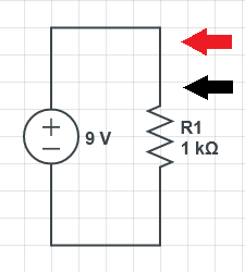
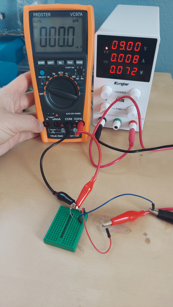
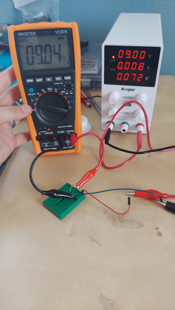
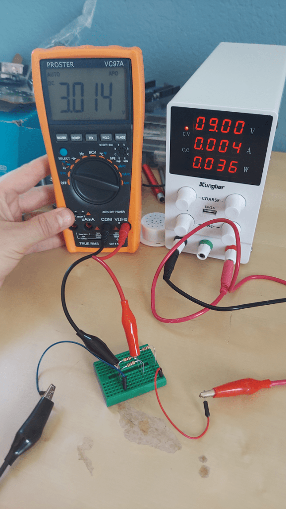
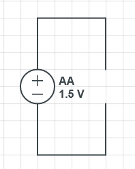
First let’s look at a single resistor in a circuit. Lets put a 1000 ohm resistor in a circuit with a 9 volt battery. If we connect our multimeter probes to the wire on the same side of the resistor and measure volts we’ll get zero volts (see diagram below). This is because volts is a measurement of electric potential between two points. Our multimeter is measuring the difference in electric potential between two points right next to each other on a wire, and the difference is essentially zero. The red and black arrows on the circuit diagram are where we connect the red (+) and black (-) probes of our multimeter.(Tangent: 9 milliamps is going through this circuit since there is 1000 ohms of resistance and 9 volts. The power supply says 8 but it has limited accuracy, resistors are not exactly their labeled value, wires have resistance, etc. It also reads that there are 9 volts * 8 milliamps = 72 milliwatts of power being used.)
(Circuit diagrams made at https://www.circuitlab.com/editor/)
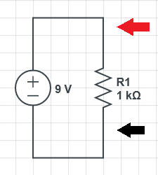
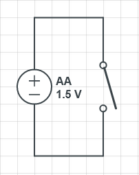
What if we put our multimeter on different sides of the resistor? In that case, we read 9 volts. The resistor makes it more difficult for electricity to cross, and thus there is a difference in electric potential of 9 volts, on each side.
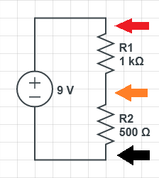
What would happen if we put two resistors in?
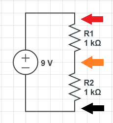
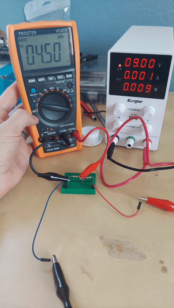
If we measure at the red and black arrows again, we’ll still have 9 volts. If we measure at the red and orange arrows though, we’ll see 4.5 volts. If we read at the orange and black arrows, we’ll also see 4.5 volts. We know that the whole circuit needs to go from 9 volts to 0 volts since that is what is provided by our battery, but it dropped by half on the first resistor, and then dropped the rest of the way on the second resistor. (Tangent: the total resistance here is 2000 ohms, so 4.5 milliamps would flow through the circuit)
Let’s change the value of the resistors and see what happens.

I didn’t have a 2000 ohm resistor so i just put two 1000 ohm resistors in series (more on that further down).

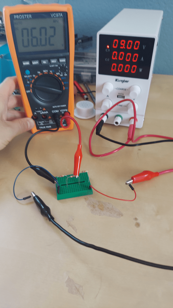
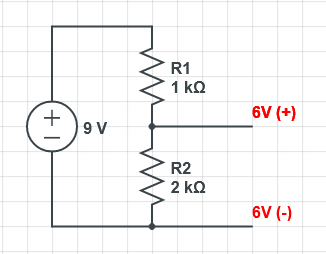
If we measure between the red and black, we still have 9 volts. If we measure between the red and orange, we get 3 volts though, and if we measure between the orange and black, we get 6 volts. Weird! (Tangent: The total resistance here is 3000 ohms, so there should be 9 volts / 3000 ohms = 3 milliamps flowing through the circuit but my power supply isn’t showing that correctly.)
Similarly, you can change the second resistor to be half instead of double and get the opposite result.
I didn’t have a 500 ohm resistor so i put two 1000 resistor ohms in parallel (more on that further down).
What is going on here is that the 9 volts are dropping off across the resistors based on their relative values. When the resistors are equal in value, they each get half of the voltage. When they are unequal, the voltage across the R2 resistor is calculated like this:

To actually use this as a power source, you would connect new wires as the positive and negative power for a sub circuit.
Note in the above, I’m not saying that is -6V and +6V, which would be 12 volts total, I’m just labeling the positive and negative sides of the 6 volts of power available.
You could use the top part as a 3 volt source if you wanted instead, or in addition to the 6 volts you are using from the bottom part. You could even split the voltage into more than just two levels, but instead could put in N resistors to have N voltage levels.
The famous 555 timer for instance internally uses a voltage divider with three 5K resistors to make three different power levels, and that is why it’s called a 555 interestingly. You can see it at the top of this diagram of a 555 timer, between the ground (pin 1) and the +Vcc supply (pin 8).

(This image is from this 555 timer tutorial: https://www.electronics-tutorials.ws/waveforms/555_timer.html)
Resistors in Series vs in Parallel
When I needed a 2k Ohm resistor in the last section I put two 1k Ohm resistors in series. When you put resistors in series, their values add together, allowing you to additively create whatever resistance you need.
When I needed a 500 Ohm resistor and didn’t have one, I put two 1k Ohm resistors in parallel. This is because putting resistors in parallel gives electricity more than one path to get through, and thus has lower resistance than if there was only one of the resistors. The exact equation for the resistance of resistors in parallel is:

Where 
This means that if you put two of the same valued resistors in parallel, the resistance will be cut in half. If you put three of them in parallel, the resistance will be cut in three.
This formula comes up again in electronics. For capacitors, when you put them in parallel, their capacitance adds. When you put them in series, their capacitance follows the parallel resistor equation. It’s the same formulas, but parallel / series reversed. Strange huh?

Where 
Something else strange is that this is why thicker wire has less resistance too. There are more paths for electricity to travel through the thicker wire, compared to thinner wire, so resistance goes down.
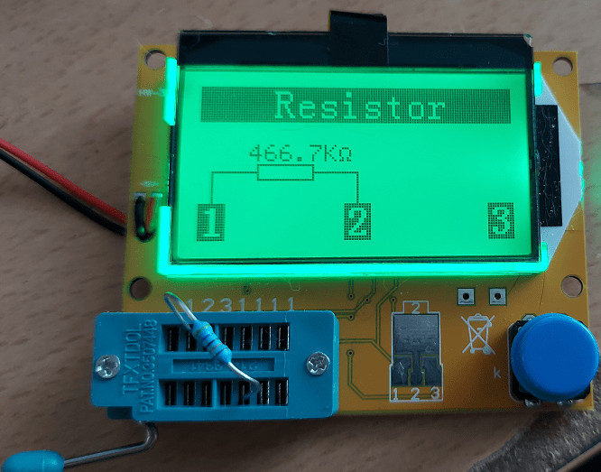
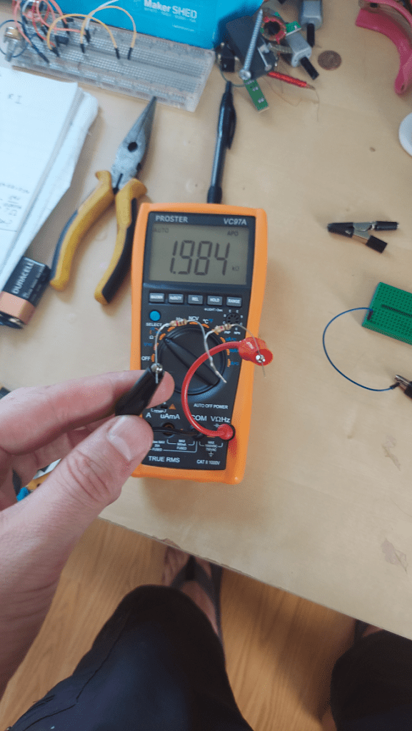
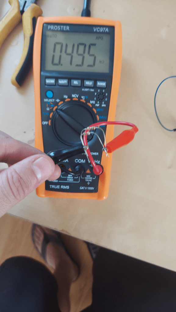
Below are some images of two 1k Ohm resistors in series and in parallel, with the multimeter showing the total resistance value.
One resistor:
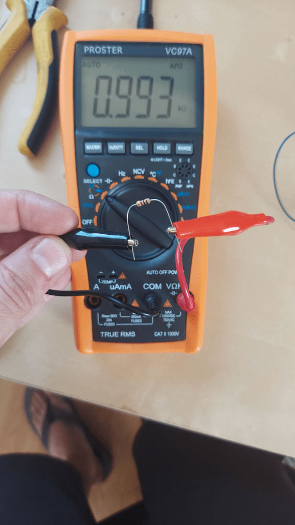
Two resistors in series:
Two resistors in parallel:
What Happens When Using a Voltage Divider?
Ok so let’s start with the voltage divider we set up before.
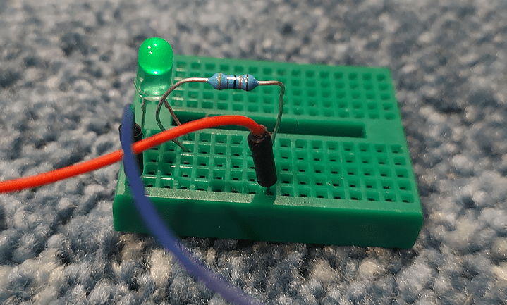
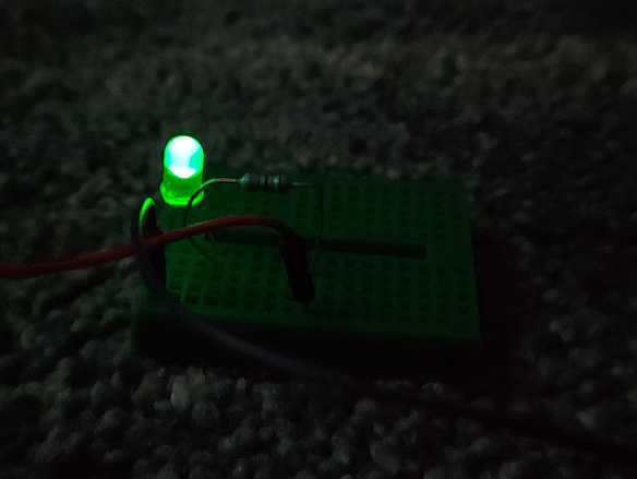
Now let’s say we actually use that 6 volts to power something. That something will have a resistance of 2k Ohms. Maybe it’s some kind of light bulb.
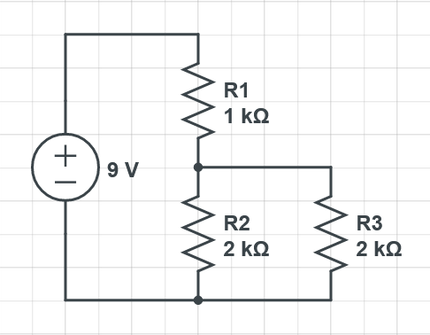
We can simplify this circuit though. The 2k Ohms of our load, and the 2k Ohms of the voltage divider are in parallel so we can use our formula for parallel resistance, or remember that two capacitors of equal value in parallel get half the resistance. So that means we could describe our circuit this way, as far as resistance is concerned:
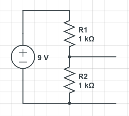
The problem with that is that our voltage divider has changed. The resistors are equal now, which means that our 6 volts has dropped down to 4.5 volts!
If we decreased the resistance of what we were powering, the voltage would drop too. Intuitively, imagine if you had a short circuit so had zero resistance across the load, the electricity would completely bypass the 2k Ohm resistor in the voltage divider as if it weren’t there, so there would be zero volts difference between the top and bottom of the 2k Ohm resistor.
If we increased the resistance of what we were powering, we would raise the combined parallel resistance there on the 2nd part of the voltage divider, but luckily would at most have 2k ohm resistance. For instance, using a 1 mega ohm resistive load, the parallel resistance formula gives us a resistance of 1.996 k Ohms. So, if we had a high resistance load, we’d get nearly our full 6 volts, but would never quite have the full 6 volts. At the limit, if our load was disconnected, and thus had infinite resistance, we would get the full 6 volts.
If you know the resistance of the load you are plugging into the voltage divider, you can take it into account and choose a resistor for the voltage divider that gives you the desired parallel resistance amount and thus the right voltage. Some loads have variable resistances though, and then you have a problem and should look at other methods of changing the DC voltage level, such as a buck converter.
Some loads have no resistance though, and a voltage divider can come in really handy. Supplying power to a transistor’s base, or to an op amp’s input, or to an optocoupler’s input for instance can make great use of these because they just “read” the voltage signal there without putting any extra load on it.
The lesson here is that whenever you plug things together, you might get strange drops in voltage because you’ve accidentally created a voltage divider. If your resistance is sufficiently higher than whatever internal resistance what you’ve plugged into has, you can ignore the voltage drop, but that also decreases the amperage so may not be desirable.
This effect even comes up in batteries (and other power sources) which essentially can be modeled as an ideal voltage source, with a small resistance (like 10 ohms). If you use a low valued resistor on a battery, the voltage will drop because you are secretly part of a voltage divider involving the internal resistance of the battery (and in fact, that “internal resistor” can’t take that much power and will start heating up, which can be dangerous! So don’t short circuit batteries!). Since a battery’s resistance is so small, your resistance level is likely to be much higher when using the battery to power something, and this isn’t something you really have to worry about in normal situations.
Of course, all this talk only deals with DC and resistors. Things get more complex when you have capacitors, inductors or AC power.
Maximum Power (Watts)
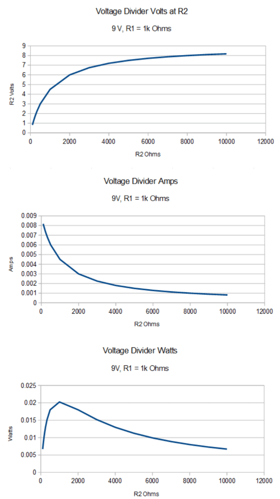
So we saw that as R2’s resistance gets larger, the voltage across R2 becomes larger, and at infinite resistance, it gets all the voltage available.
We also know that the larger the resistance, the lower the amps in the circuit, so getting that voltage comes at a cost.
Watts is a unit of measurement of power and is volts multiplied by amps. It turns out that if you want your voltage divider to have maximum power (watts), that R1 should equal R2. Wikipedia has more about that here: https://en.wikipedia.org/wiki/Impedance_matching
Here are some graphs showing this, where if resistor R1 is 1k Ohms, that you get the highest amount of watts when R2 is also 1k Ohms, despite the behavior of the volts and amps.
Calculating Resistance (and Voltage) of an Unknown Circuit
Since plugging your circuit into other things can make an implicit / unintentional voltage divider, you probably want to know how much resistance some other black box circuitry might have. Luckily you can figure this out using Ohms law (see last post: Voltage, Amps, Resistance and LEDs (Ohm’s Law)) and some simple algebra.
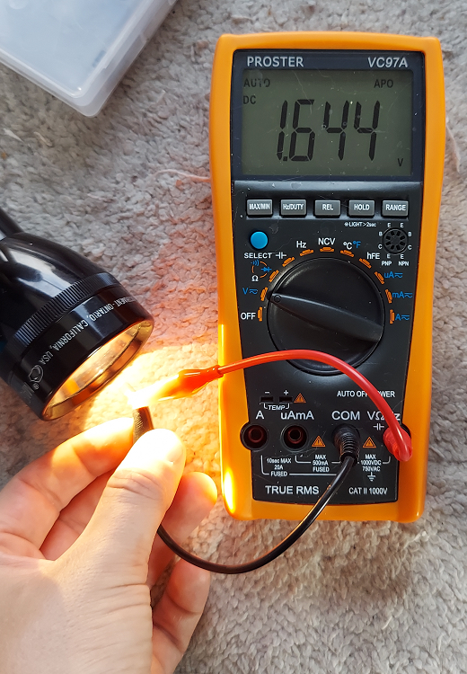
First, connect a resistor to the + and – and measure the amps in the circuit. If you use a resistor that is too low value, or has too low of a wattage rating, the resistor will get hot, possibly start glowing or burst into flames (resistors have a rating in watts and the common ones for small electronics like those seen in this post can handle 1/4 of a watt). So basically be careful if doing this with high voltages – and in fact, if my blog is your primary source of knowledge, please don’t mess with high voltage 🙂
So let’s say we connect a 1k Ohm resistor and read a value of 0.01 amps or 10 milliamps.
Ohms law says:

where I is current, V is volts and R is resistance.
So we now have this formula:

We have one equation with two unknowns, so we need another equation to make it solvable by having two equations and two uknowns. Let’s say we take an amperage measurement using a 500 Ohm resistor and get 0.017 amps or 17 milliamps.
That gives us a second equation:

We now have two equations with two unknowns!
We can solve the first equation for V and get:

From there we can plug V into the second equation to get:

Solving for R1, we get:

If you do the calculations, you get 214.28 ohms, which means the unknown circuit has that much resistance.
What’s nice is that you can also use this to get the total amount of voltage available to this circuit by plugging this resistance into the first equation that we solved for V:

This was a toy example i made up, using 12 volts and 200 ohms of resistance, so our answer is pretty close. The inaccuracies came from rounding off the numbers, but you’ll get the same problems in real life from not completely accurate measurements and imperfect electronic components.
For convenience, here are the equations to calculate the resistance of an unknown circuit, without having to do the algebra each time.
Where 


Once you have the
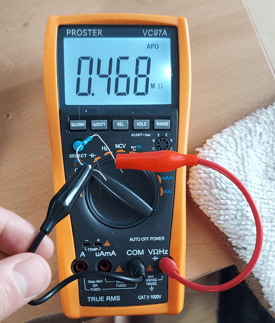
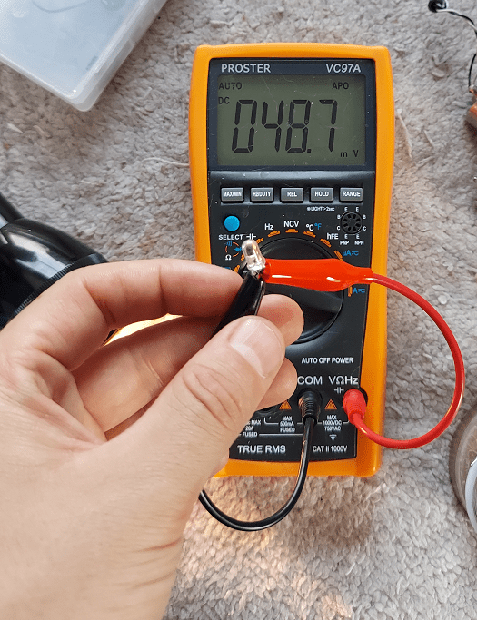
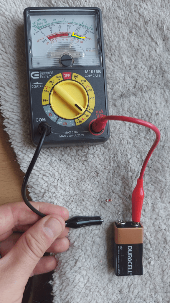
Let’s take these equations for a spin with a battery. I accidentally popped the fuse on my digital multimeter and can’t use it to measure amps so i’ll use my analog multimeter.
First i’ll measure the amps with a 1k Ohm resistor. The knob is set to 10 milliamp measurements so the bottom row of readings (that are labeled 0 to 10) are where you read from. I drew some yellow to show you where to read from. I read 8.6 milliamps.
Next i’ll put two 1k Ohm resistors in series to make 2k Ohms of resistance and measure amps to get what looks like 4.6 milliamps.

Ok so let’s plug our values into the equations!


So it looks like this 9 V battery has 150 ohms of resistance. I’ve heard that as a battery is used, it’s resistance goes up, so maybe this battery is nearing needing to be replaced having such large resistance.
Let’s calculate how many volts it has.


So, the battery has 9.89 volts inside of it. Either they made the battery have higher than 9 volts inside of it, to account for internal resistance dropping the output voltage, or my 5$ analog multimeter is not very accurate and these are just ball park figures.
Closing
Thanks for reading and hopefully you found this interesting or useful.
Have any requests or ideas for other topics to write about? Drop me a message on twitter at @Atrix256.


 . So if you see
  that means 5 Ohms of resistance. If you see
  that means 5 kiloohms which is 1000 times as much resistance. If you see
  with a capitol M, that means 5 megaohms, which is 1000 times as much resistance again.