This post talks about how to make a circuit where you press a button to turn off a light, and also explains how and why it works.
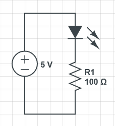
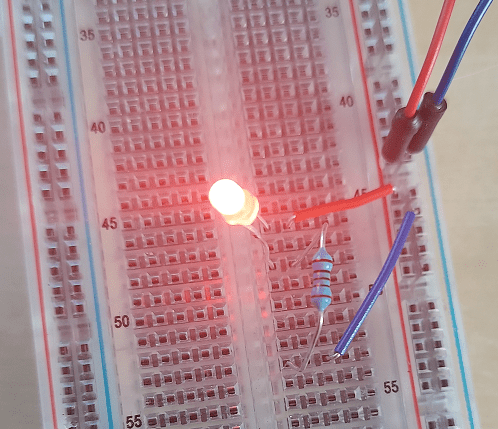
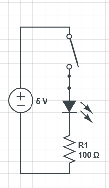
Here’s a circuit lighting up an LED (diagram made in https://www.circuitlab.com/editor/). 5 Volts is powering the circuit and the LED has a voltage drop of 1.85 volts, leaving 3.15 volts. Those 3.15 volts are put across a 100 ohm resistor, resulting in 32 milliamps of current through the circuit. That is a bit high for the LED but my power supply is showing 25 milliamps of current actually going through the circuit, which is more in line with the actual limits of the LED.
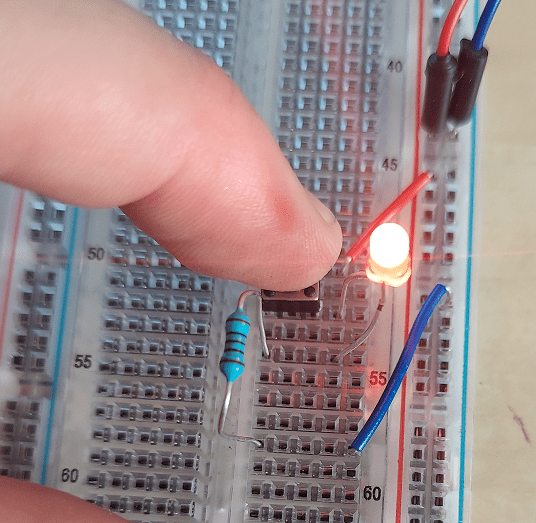
We can add a switch, so that the light is off until we press the button to turn it on. When the button is pressed, it closes the circuit and allows electricity to flow.

What if we want a circuit where the light is on until we press the button, and then the light turns off?
To make that happen, the basic idea is that you have a switch that when pressed, connects the circuit to a lower resistance path to ground. it can’t be a zero resistance path to ground though, because then it would be a short circuit, draw a lot of current, and your components could heat up and catch fire.
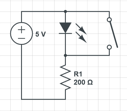
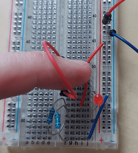
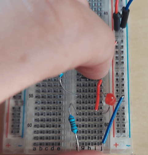
Here i make a circuit through the LED with 200 Ohms of resistance, making 16mA. When the button is pressed, another path opens up though which is 100 Ohms of resistance into ground (32mA).
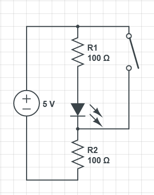

Since there is less resistance when the button is pressed, there is more current and more power being used when the LED is off (!!!). My power supply says 11 milliamps / 55 milliwatts when the button isn’t pressed, and 45 milliamps / 225 milliwatts when the button is pressed, and the light is off. Interesting that turning off a light would use more power, isn’t it? To help lower the current draw when the button is pressed, you could replace the 2nd resistor with a higher resistor value, but that will also lower the current when the button isn’t pressed, and so make the LED dimmer.
You could keep the same overall resistance but have more of it in the 2nd resistor and less in the first resistor. At best it would make it so pressing the button only used a tiny bit more power than when it wasn’t pressed, but this setup will make it always use more power when the button is pressed.
Why Does Electricity Completely Bypass The Resistor and LED?
You might wonder why when the switch is closed, making the circuit below, that the electricity seems to completely bypass R1 and the LED. The circuit is connected, so shouldn’t some go through R1 and the LED too? What prevents that from happening?

This gets doubly strange when you realize that while there is no resistor on the path where the switch was, the wire itself does have resistance, so it’s like there is just a very small resistor on that path. Wires have effects on both voltage (voltage drops across sections of them) and current, just like resistors do, so why is this configuration special?
First let’s look at the current in parallel resistors. We’ll start with two 100 Ohm resistors in parallel off of a 5 volt source.
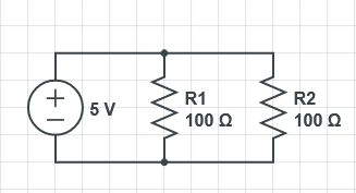
First we can calculate the equivalent parallel resistance of these two resistors. When resistors are in parallel, the effective resistance actually drops. The formula for equivalent parallel resistance is:

So for these, 1/R = 1/100 + 1/100 = 1/50. So, R = 50, meaning these two 100 Ohm resistors in parallel are equivalent to this:
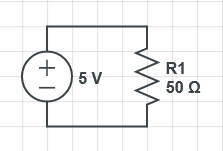
50 Ohms of resistance at 5 volts means you get 5 volts / 50 ohms = 0.1 amps of current through either circuit.
When a circuit splits though like in the circuit with two 100 ohm resistors, the current splits as well and is divided, possibly unevenly, across those paths.
Paths with lower resistance get more percentage of the current. The formula for current through a resistor in a set of parallel resistors is:

Calculating it for R1, we have: (0.1 * 1/100) / (1/100 + 1/100) = 0.001 / (2/100) = 0.05 amps.
It isn’t real surprising that it gets half the amount of amps, since both resistors are the same value. They each get half the current.
What if we change the resistors to have values of 190 Ohms and 10 Ohms respectively?
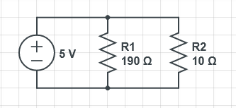
First up, we can calculate the equivalent parallel resistance: 1/R = 1/190 + 1/10. R = 9.5 Ohms. At 5 volts, we get 5 volts / 9.5 ohms = 526mA of current.
Let’s now calculate how much of the current goes through the 190 Ohm resistor.
(0.526 * 1/190) / (1/190 + 1/10) = 0.026A or 26mA.
Let’s calculate how much goes through the 10 Ohm resistor.
(0.526 * 1/10) / (1/190 + 1/10) = 0.5A or 500mA.
Most of the current by far is now going through the 10 Ohm resistor, the smaller resistor. As R2 gets smaller and approaches 0 Ohms of resistance, like a wire would also approach, it’s going to approach taking all of the current, since one divided by the resistance controls what percentage of the current is taken down that path, and 1 divided by a very small number is a very large number.
That’s the intuition for why current will almost 100% go through the open wire in the circuit with the switch when it’s available. When you put resistors in parallel like this, it’s actually called a current divider, much like a previous post showed how to use resistors to make voltage dividers.
When the switch is pressed in our setup, a small amount of current does go through the resistor though, and tries to go through the LED as well, but there’s another thing at play here: voltage.
Voltage if you remember is the difference in electrical potential between two points. The LED requires a difference of 1.8 volts minimum to let electricity through and to light up. When the switch is pressed, the voltage is the same on the positive and negative side of the LED which means the LED has zero volts and does not light up or let electricity flow through it. Let’s explore why that is…
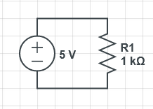
In this circuit, there is 5 volts, a total of 1000 Ohms, and so 5mA of current. The voltage drop across R1 is the full 5 volts.
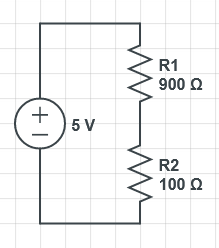
This circuit also has 5 volts, 1000 Ohms total, and 5mA of current. To calculate the voltage drop of the resistors, you use Ohms law of the form V = IR. You multiply the current of the circuit by the resistor value to get the voltage drop across the resistor. For R1 it’s V = 0.005A * 900 Ohms = 4.5 volts. For R2 it’s V = 0.005A * 100 Ohms = 0.5 volts.
You can see that the larger resistor got more voltage drop, while the smaller resistor got almost no voltage drop.
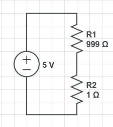
This circuit has the same voltage, total resistance, and current. Skipping ahead to calculating the voltage drop across the resistors, R1 is 0.005 * 999 = 4.995 volts. R2 is 0.005 * 1 = 0.005 volts. As R2 approaches zero, the voltage drop also approaches zero. This is why in our original circuit (below), when the switch is closed, there is (almost) no voltage drop across the wire on the right, meaning the voltage above R1 and the voltage below the LED are the same, so there is 0 volts going through the path of the circuit that has an LED on it. This along with the nearly zero current trying to go through there as well.
If you want to know more about this stuff, give this a read: https://learn.digilentinc.com/Documents/345
There is also a neat technique to do these sorts of calculations called nodal analysis: https://www.youtube.com/watch?v=f-sbANgw4fo
There is another technique called mesh analysis: https://www.youtube.com/watch?v=eQpc2QRFv7Y
Alternatives To This “Off Button” Circuit
The fact that the circuit uses more power when the light is off is pretty bad, so you are probably interested in some alternatives.
The button I am using is called “single pole single throw” switch. The single pole means that there is one electrically connected input, and the single throw means that it only has one output that the input is connected to or not. Double pole switches are switches that can control two different circuits with the same button/switch – you can turn on two different parts of a circuit when one button is pressed. Double throw switches are switches that connect to one output if the button is pressed, and a different output if the button is not pressed. Using a double throw switch in the last circuit, you could hook the LED up to the output for when the button was not pressed, and you could leave the other output disconnected, for when the button was pressed. That would make it use no power when the light was turned off, instead of using more power.
With all this talk of switches, you may be wondering if there’s a switch that you can turn on and off with electricity, instead of requiring a human to actually press a button. There are in fact such things! There is something called a relay, which when it is given power, it powers an electromagnet inside of itself and closes a switch using that magnetism. You can actually hear them click as they turn on and off! Much more common for this task are transistors though, which allow small amounts of electricity to control the flow of larger amounts of electricity. This allows them to be used as electronic switches, but also allows them to work as amplifiers. It would be fun to write a blog post about them at a future point. Transistors can be used to make circuits that invert a button press value too though. At that point, we are basically talking about a NOT gate.
Thanks for reading!
Addendum
Someone pointed out to me that LEDs themselves have internal resistance, so you could move all the resistance down into the shared path. This works because the LED has internal resistance. The nice thing about this is that when the button is pressed, it only uses 25mA instead of 50mA. I tested it and it does indeed work!