
“Scratch a Pixel” has a really nice explanation of perspective and orthogonal projection matrices.
It inspired me to make a very simple / plain explanation of orthogonal projection matrices that hopefully will help them be less opaque for folks and more intuitive.
Original article: Scratch A Pixel: The Perspective and Orthographic Projection Matrix
Let’s Get To It!
The whole purpose of an orthogonal matrix is to take x,y and z as input and output x,y and z such that valid points on the screen will have x,y,z values between -1 and 1.
If we transform a point and get an x,y or z that is outside of that range, we know the point is outside of the screen either because it’s too far left, right, up or down, or because it’s too close or too far on the z axis.
Let’s think about how we’d do this, thinking only about the x coordinate for now.
To map some range of x values from -1 to 1, we’ll need to decide on what x value maps to -1 and what x value maps to 1. We’ll call these “left” and “right”.
Given a left and right value, and an x value we want to map to the range, perhaps the most straight forward way to do it would be this:
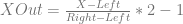
The division calculates the percentage of how far X is between left and right. Multiplying that by 2 and subtracting 1 changes it so instead of valid points being from 0 to 1 (aka from 0% to 100%), they are instead between -1 and 1.
Let’s change this formula so that there is one term that is multiplied by X and another term that has everything else. (Wondering why? It’s because I’m cheating and know the final form. Don’t feel bad if it isn’t intuitive why we’d do this!)
Setting up the formula this way allows us to transform the x component of an (x,y,z,1) point using a dot product:

A dot product is what happens during matrix multiplication, so if we put this into a 4×4 matrix, we get the same result. Let’s check that out.
We start with an identity matrix. If we use it to transform an (x,y,z,1) point, we get the same point as output aka nothing happens.

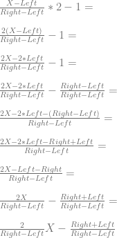
Now let’s put the x transform we came up with into the matrix:
If we use that matrix to transform an (x,y,z,1) point, it will transform our x component as we described (valid ranges of x that are between left and right will be between -1 and 1), while leaving the other components of the point alone.
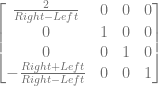
As you might imagine, it’s pretty simple to get our formulas for y and z as well. Starting with the x formula, we can just change x with y and z, and right/left with top/bottom and far/near.
We can put those into our matrix to get a full orthographic projection matrix.
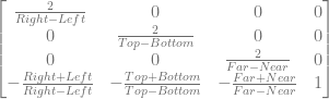
There we go, that’s all there is to making an orthographic projection matrix. It’s whole purpose is to convert x,y,z values to be between -1 and 1 so that the GPU knows whether points are inside our outside the screen – and thus whether they need to be clipped or not.
Variations
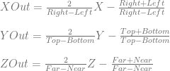
While the projection matrix we made is a valid orthographic projection matrix in OpenGL, we actually need a tweak for it to be valid for DirectX. The reason for this is because while in OpenGL the clip space for z is between -1 and 1, it’s actually between 0 and 1 for DirectX!
If you leave off the *2-1 for the z formula, but leave it for x and y, you’ll end up with a matrix like this one:

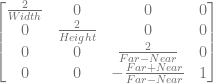
Another variation you’ll see is a version where the camera is centered on the origin for the x and y axis. In other words, left = -right, and top = -bottom. When that is true, right+left and top+bottom become zero which simplifies the matrix to this:
Another variation you’ll see is that the matrix is transposed. You’ll see this when switching between pre and post multiplication, or when switching from column major matrices to row matrices. Either is valid and it’s basically just a notation and convention thing. Here is the origional matrix we made transposed.

Lastly, the above matrices were all for a “left handed” system. That means that it assumes the positive x axis goes to the right, the positive y axis goes up, and the positive z goes into your screen (aka, the camera is looking down the positive z axis). Positive Z values will map to the valid -1 to 1 range, while negative z values will be outside the valid range.
A variation on the orthographic projection matrix we made that you’ll see is the matrix being a “right handed” matrix which is the same as the left handed matrix, except that the positive z axis goes out from your screen (aka the camera is looking down the negative z axis). Negative Z values will map to the valid -1 to 1 range, while positive z values will be outside the valid range.
To switch the handedness of the matrix, you just flip the sign of the element at (3,3), so here is our original orthographic projection matrix, but converted to right handed instead of left handed.
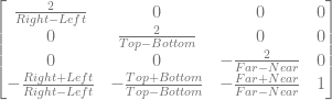
You may also just see the denominator changed from 


Fun trivia: the term “sinister” comes from latin, meaning “left handed”. So, when talking to someone about their graphics engine, you can ask them whether or not they use sinister projection 😛
Links
Scratch A Pixel: The Perspective and Orthographic Projection Matrix
D3DXMatrixOrthoRH (DirectX) – shows the resulting matrix. Also links to left handed and off center variants.
glOrtho (OpenGL) – shows resulting matrix.
