
I’ve taken up learning electronics during the pandemic, and have enjoyed it quite a bit. I’ve been programming for 25+ years, so it’s nice to have something different to learn and work on that is still both technical and creative. It’s cool getting a deeper understanding of how the fundamental forces of nature work, as well as being able to MacGyver a hand crank powered flashlight from an old printer if needed (Check out a 40 second video of that here!). It’s also nice having something physical to show at the end of the day, although it does require consumable parts, so there are pros and cons vs making software.
Friends (Hi Wayne!) and YouTube have helped me learn a lot, but I found the subject pretty alien at first and wanted to try my hand at some explanations from a different POV. This post starts that journey by taking the first steps into DC electronics.
Ultra Basics
Electricity flows if there is a path for it to flow in and the flow is made up of electrons.
Electrons are negatively charged so travel from the negative side of a circuit to the positive side.
Conventional current flow is backwards from this though, and says that electricity flows from the positive side to the negative side. In this case, it’s not electrons flowing but “holes” flowing. Holes are a weird concept, but they are just a place that will accept an electron.
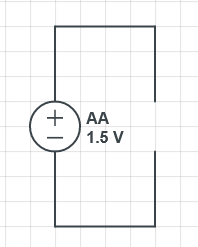
Here is an open circuit, which means that there is a gap. Since the circuit is not closed, electricity cannot flow. (made in https://www.circuitlab.com/editor/#)
If you close the circuit, like the below, electricity is able to flow.

The circle on the left is a power source with a + and – terminal. It’s labeled as a 1.5 volt double A battery.
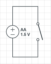
Here is a diagram of a circuit with a switch that can be used to open or close the circuit. Being able to read and make circuit diagrams is real helpful when building things or trying to understand how circuits work.
Of note: the higher the voltage, the farther that electricity can jump across gaps. So, while at low voltage, a circuit may be open, turning up the voltage may make it closed when the electricity arcs across!
Ohm’s Law

IMAGE CREDIT: Eberhard Sengpiel
The most useful thing you can learn about DC electricity is Ohm’s law which mathematically explains the relationship between voltage, amperage and resistance. Ohm’s law is:

In the equation I stands for Intensity and means current aka amps, V stands for voltage and R stands for resistance.
If electricity was water, voltage would be the water pressure, amperage would be how much water was running through the pipe, and resistance would be a squeezing of the pipe, like in the image above.
Current is measured in amperes (amps) or the letter A. 500mA is 500 milliamps, or half of an amp, and 1.2A is 1.2 amps. Note: electricity is dangerous! It can take only a few hundred milliamps to be fatal, but voltage is needed to be able to let those amps penetrate your skin.
Voltage is measured in volts or the letter V. If you see 9V on a battery, that means it’s a 9 volt battery, and is capable of providing 9 volts.
Resistance is measured in Ohms or the omega symbol 


Where Ohm’s law comes in handy is when you know two of these three values and you are trying to calculate the third one.
As written, the formula showed how to calculate amps when you know voltage and resistance, but you can use algebra to re-arrange it to a formula for any of the three:


This comes up quite often – if you know how much voltage a battery has, and you know how many amps you need, you can use this to calculate the value of the resistor to get the desired amps.
Diodes, LEDs and Resistors
LED stands for Light Emitting Diode. A diode is something which lets electricity only flow in one direction and it has a couple of common uses:
- Protecting circuits from electricity flowing in the wrong direction.
- Turning Alternating Current (AC) into Direct Current (AC) by rectifying it (preventing the negative part of AC from getting through. Same as last bullet point)
- Lots of cool tricks, like stabilizing uneven power levels by letting voltage over a specific value “spill over” out of the circuit.
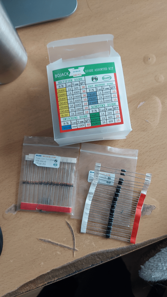
Here is a pack of various diodes i bought from amazon for 10$. There are a quite a few different types of diodes, which are useful for different situations.
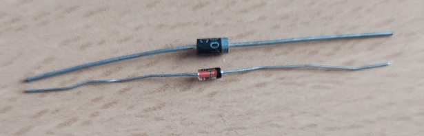
Here are some diodes close up. The black one is a rectifier diode IN4001, and the more colorful one is a switching diode 1N4148. Those part numbers are actually written on the diodes themselves but are a bit hard to see. You can use these numbers to look up the data sheet for the parts to understand how they work, what their properties are, how much voltage and amps they can handle, and often even see simple circuit diagrams on using them for common tasks. Data sheets are super useful and if doing electronics work, you will be googling quite a few of them! Here is the data sheet for 1N4148 which i found by googling for “1N4148 data sheet” and clicking the first link. 1N4148 Data sheet.
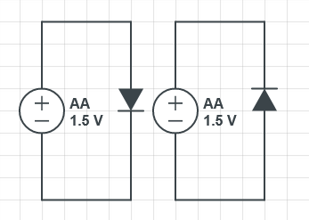
Here are two circuit diagrams with diodes in them. The black triangle with the line on it is a diode. The arrow shows the direction that it allows conventional flow to travel. The line on the arrow corresponds to the bands on the right of the diodes in the image above, which is the negative side of the diode (cathode). The left circuit is a closed circuit and allows electricity to flow. That diode is forward biased. The circuit on the right has the diode reverse biased which does not allow electricity to flow.
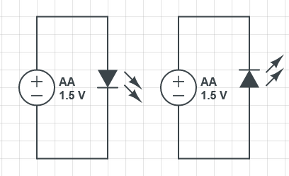
LEDs can do many things regular diodes can do, since they are diodes, but they have the property that when electricity flows through them, they light up. Since they are diodes, and only let electricity flow in one direction, LEDs have a + side and a – side and you have to hook them up correctly in a circuit for them to light up. If you hook them up the wrong way, it doesn’t damage them, but they don’t light up and they don’t close the circuit for electricity to flow. The symbol for an LED is the diode symbol, but with arrows coming out of it.
Here are a pack of LEDs i have that came as part of a larger electronics kit. You can get a couple hundred LEDs in a variety of colors from amazon for about 10$. Some LEDs are in colored plastic cases, some are in clear cases. There are even LEDs that shine in infrared and ultraviolet. LEDs also come in different sizes. This pack has 3mm and 5mm LEDS.

Here is an up close look at a white LED. The longer leg is the positive side, which means you need to plug the positive side of the circuit into it if you want it to light up. the negative side has a shorter leg, but the negative side also has a flat side on the circular ring at the bottom, which can’t really be seen in this picture.

All diodes have a voltage drop, which is a voltage amount consumed by the diode. If you are providing less than that amount of voltage, the diode will act as an open switch, and electricity won’t flow through it. The specific voltage drop for diodes can be found in data sheets, but i’ve found it difficult to find data sheets for LEDs. Luckily I picked up a “Mega328” component tester from amazon for 15$. It lets you plug in a component, press the blue button, and then tells you information about the component. It’s super handy! Here you can see the voltage drop of 2 different LEDs. The smaller red LED has a voltage drop of 1.88V while the larger green LED has a voltage drop of 2.5V. If you supply them with less than that amount of voltage, they will not light up!


So what would happen if we tried to connect the LEDs to the batteries below?
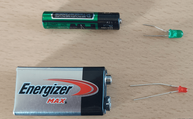
The large green LED has a 2.5V voltage drop, while the AAA battery only has 1.5V as you can see on the label. That means the LED doesn’t light up.
The smaller red LED has a 1.88V voltage drop and is connecting to a 9V battery so it has enough voltage and should light up. Let’s use Ohm’s law to calculate how much current – in amps – are going through the LED.
I = V/R and in our case V is 9 and R is 0 because we have no resistance.

Oops we have infinite current! The LED is destroyed pretty quickly after you plug it in.
There isn’t actually infinite current, because the metal wires connected to the LED have a very tiny amount of resistance to them, just like all wire, and the battery has a limit of how many amps it can give. So in any case, it isn’t infinite amps, but it is a very large number, limited by how many amps the 9V battery can actually deliver. The LED would actually be destroyed. You should basically always use a resistor with an LED to limit the current and keep it from being destroyed. Here is an interesting read about how to calculate the internal resistance of a battery which will then tell you how many amps it can give you: Measuring Internal Resistance of Batteries.
When you have a circuit with this low of resistance, it’s considered a short circuit, and if the LED didn’t get destroyed, the battery would start getting hot and it could become a dangerous situation. This is also why short circuits themselves are bad news. They have a LOT of current running through them which can cause things to heat up, melt and catch fire.
3mm and 5mm LEDs typically want 20 milliamps maximum (20mA or 0.02A) to be at full brightness. If you give them less, they will be less bright but still function.
We can calculate then how much resistance they want to be maximally bright if we know the voltage of the power source we are using and the voltage drop off of the LED we are trying to power.
Let’s take the larger green LED with a 2.5V voltage drop, and power it with a 9V batter, aiming to get 20mA.
First we subtract the voltage drop from the supply to see how much voltage we have to work with: 9V – 2.5V = 6.5V.
Next, we know we want 20mA and we have 6.5V, and we are just trying to solve for resistance so we use Ohm’s law: R = V/I.

So, we need 325 ohms of resistance to get 20mA in our LED from a 9V battery. Here is a pack of resistors i got from amazon for 12$.
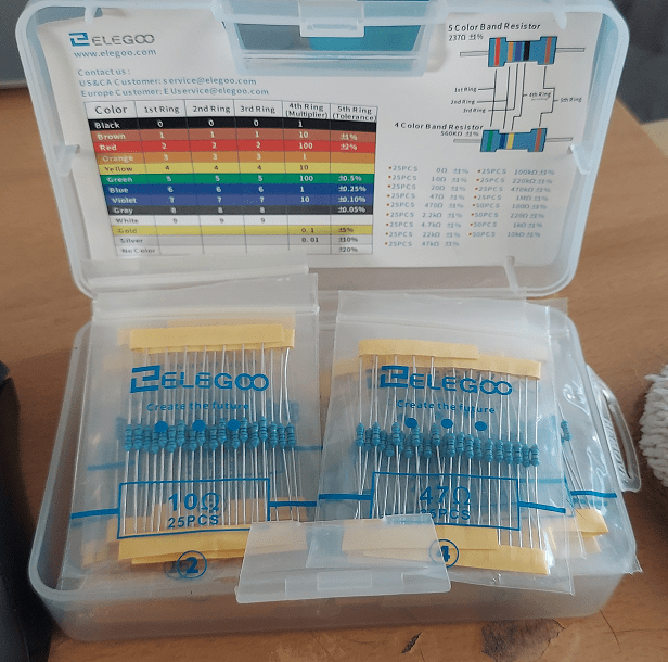
Resistors have funny colored bands on them which tell you their rating. You can find charts for decoding them all over the place, but again, the “Mega328” will tell you this too.
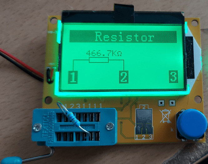
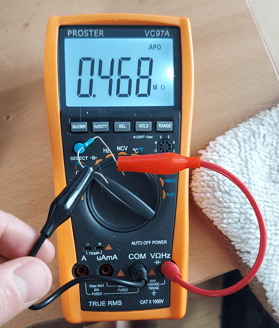
In fact, a multi meter will tell you as well. Multi meters aren’t very expensive. Here’s one i got from amazon for 35$ which has tons of features and works really nicely.
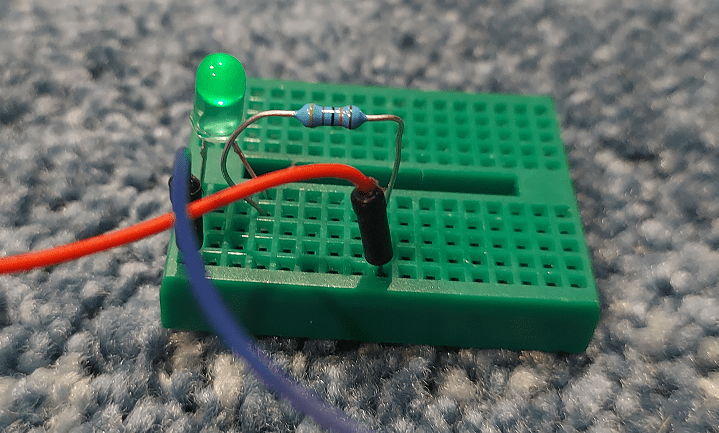
I don’t have any 325 ohm resistors, but i do have 470 ohm resistors, so i’ll just use one of those. That’s 14mA if you do the math, which is a bit lower than 20mA, but it still works just fine despite not being as bright as it could be. You can get different resistances by connecting resistors in parallel or series and doing some math, but this works for now. I used a mini breadboard (the green thing) to hook this circuit up. Every horizontal line of 5 holes is connected to each other electrically. It’s a nice way to play with circuits without having to solder things together. By convention, red is used for the positive terminal and black or blue is used for the negative.

By the way, quick fun fact. A 1.5V AA battery is considered dead when it has dropped down to 1.35V. At this point, it still has energy in it though! If you are clever with electronics, you could make circuitry to use this power from dead batteries to give you 1.5V or higher, and you could drain so called dead batteries even further.
LEDs Turning Light Into Power
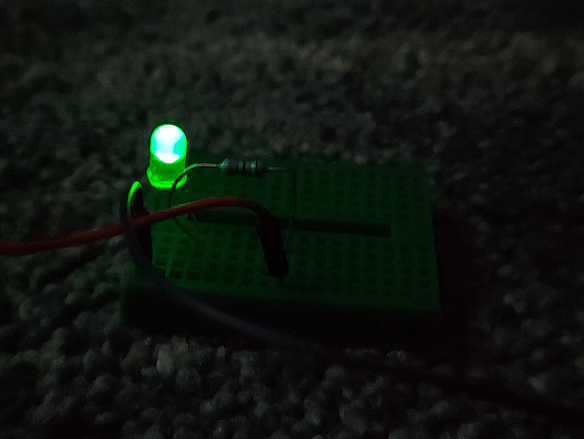
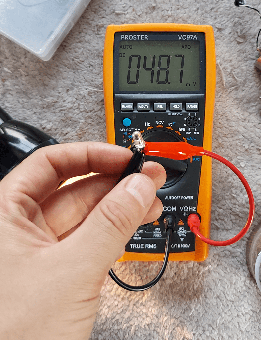
Many things in electronics turn out to be reversible. Speakers work as poor microphones, and microphones work as poor speakers. Similarly, LEDs can work as poor solar cells and turn light into energy. Want to see? Here i hook my multimeter up to an LED, and have it set to read volts. It reads 48.7mV. Energy is flowing all around us from radio waves, etc, so it’s picking up some of that.
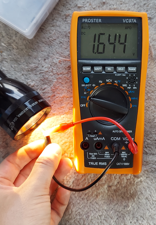
When i put the LED in the beam of the flashlight, it jumps up to 1.644V. Pretty cool huh?
Did You Like This Post?
It’s a little different than what I usually write about, but hopefully you liked it. Careful though, this stuff escalates quickly. Before you know it you’ll be harvesting optocouplers and coils from old printers to make a rail gun.

This is a fantastic post! I do think it could rekindle an old, dormant interest in physical electronics. There are very many ideas I want to try with LEDs.
LikeLike
That’s great & thanks for saying so. A fun thing i did the other day is hook up 2 LEDs to my base guitar’s (unpowered) output, one opposite direction from the other. When i played the strings really hard, the LEDs would light up – and it was both of them that would light up, showing that strumming the guitar was creating AC current 😛
LikeLike
There are so many things I like about this post. You have simple easy to understand explanations, then practical real-world experiments, and then really interesting and memorable “what would happen if” experiments that reinforce the concepts. I haven’t seen that before.
LikeLike
Pingback: Resistance and Voltage Dividers « The blog at the bottom of the sea