
In this post we are going to Frankenstein ideas from two other recent posts. If you haven’t seen these yet you should probably give them a read!
Ingredient 1: Lagrange interpolation
Ingredient 2: Rectangular Bezier Patches
Lagrange Surface
Lets say you have a grid of size MxN and you want to make a 3d surface for that grid.
You could use a Bezier rectangle but lets say that you really need the surface to pass through the control points. Bezier curves and surfaces only generally pass through the end / edge control points.
So what do you do? How about using Lagrange interpolation instead?
Just like how Bezier rectangles work, you interpolate on one axis, and then take those values and interpolate on the other axis.
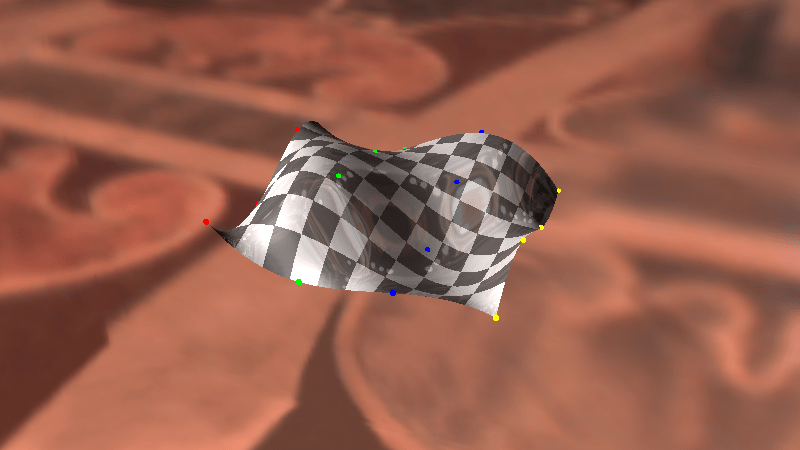
Doing that, you get something like the below:
This comes at a price though. Whereas a Bezier curve or surface will be completely contained by it’s control points, a Lagrange rectangle isn’t always. Also, they are subject to something called Runge’s Phenomenon which basically means that the more control points you add, the more likely a surface is to get a bit “squirly”. You can see this effect when you add a lot of control points to my 1d lagrange interpolation demo as well: HTML5 1d Lagrange Interpolation.
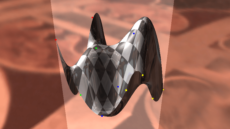
Below is a picture of a bicubic Lagrange rectangle using the same control points the cubic Bezier rectangles used. Notice how much more extreme the peaks and valleys are! In the screenshot above, i scaled down the control points to 1/3 of what they were in the Bezier demo to make it look more reasonably well behaved.
Code
#include <stdio.h>
#include <array>

typedef std::array<float, 3> TFloat3;
typedef std::array<TFloat3, 3> TFloat3x3;

const TFloat3x3 c_ControlPointsX =
{
    {
        { 0.7f, 0.8f, 0.9f },
        { 0.2f, 0.5f, 0.4f },
        { 0.6f, 0.3f, 0.1f },
    }
};

const TFloat3x3 c_ControlPointsY =
{
    {
        { 0.2f, 0.8f, 0.5f },
        { 0.6f, 0.9f, 0.3f },
        { 0.7f, 0.1f, 0.4f },
    }
};

const TFloat3x3 c_ControlPointsZ =
{
    {
        { 0.6f, 0.5f, 0.3f },
        { 0.7f, 0.1f, 0.9f },
        { 0.8f, 0.4f, 0.2f },
    }
};

void WaitForEnter ()
{
    printf("Press Enter to quit");
    fflush(stdin);
    getchar();
}

//=======================================================================================
float QuadraticLagrange (const TFloat3& p, float t)
{
	float c_x0 = 0.0 / 2.0;
	float c_x1 = 1.0 / 2.0;
	float c_x2 = 2.0 / 2.0;

    return
        p[0] *
        (
            (t - c_x1) / (c_x0 - c_x1) *
            (t - c_x2) / (c_x0 - c_x2)
        ) +
        p[1] *
        (
            (t - c_x0) / (c_x1 - c_x0) *
            (t - c_x2) / (c_x1 - c_x2)
        ) +
        p[2] *
        (
            (t - c_x0) / (c_x2 - c_x0) *
            (t - c_x1) / (c_x2 - c_x1)
        );
}

float BiquadraticLagrangePatch(const TFloat3x3& p, float u, float v)
{
    TFloat3 uValues;
    uValues[0] = QuadraticLagrange(p[0], u);
    uValues[1] = QuadraticLagrange(p[1], u);
    uValues[2] = QuadraticLagrange(p[2], u);
    return QuadraticLagrange(uValues, v);
}

int main(int argc, char **argv)
{
    // how many values to display on each axis. Limited by console resolution!
    const int c_numValues = 4;

    printf("Lagrange rectangle:n");
    for (int i = 0; i < c_numValues; ++i)
    {
        float iPercent = ((float)i) / ((float)(c_numValues - 1));
        for (int j = 0; j < c_numValues; ++j)
        {
            if (j == 0)
                printf("  ");
            float jPercent = ((float)j) / ((float)(c_numValues - 1));
            float valueX = BiquadraticLagrangePatch(c_ControlPointsX, jPercent, iPercent);
            float valueY = BiquadraticLagrangePatch(c_ControlPointsY, jPercent, iPercent);
            float valueZ = BiquadraticLagrangePatch(c_ControlPointsZ, jPercent, iPercent);
            printf("(%0.2f, %0.2f, %0.2f) ", valueX, valueY, valueZ);
        }
        printf("n");
    }
    printf("n");

    WaitForEnter();
    return 0;
}
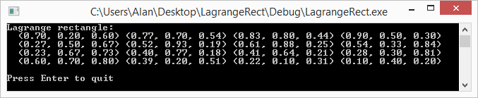
And here is the output:
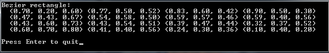
Compare that to the output of the Bezier rectangles code which used the same control points:
Links
Shadertoy: Cubic Lagrange Rectangle
Note that the above uses Lagrange interpolation on a grid. The paper below talks about a way to make a Lagrange surface without using a grid:
A Simple Expression for Multivariate Lagrange Interpolation
