
The simple standalone C++ code that goes with this post and makes autostereograms, can be found at https://github.com/Atrix256/Autostereogram.
The 1990s! They felt like a wasteland of culture at the time, but looking back, there was hyper color t-shirts, the beginning of mainstream computing and the internet, the height of alternative rock, and of course magic eye pictures.
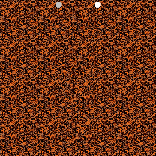
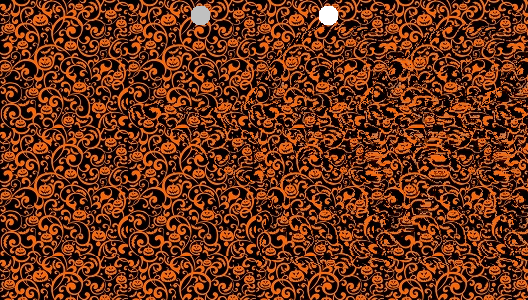
Unfocus your eyes such that the two dots overlap. A 3D image should emerge!

Quick PSA if you can’t see it!

To make an autostereogram, you need two things:
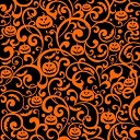
1. Color Image: A tileable repeating pattern. This can also just be “white noise”.
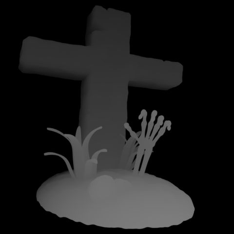
2. Depth Image: A grey scale depth map, or a black and white mask. This defines the 3D shape. Brighter pixel values are closer in depth.
For the above, I snagged these two from pintrest.
The image you are making is going to be the width and height of the depth image, but is going to have as many color channels as the color image.
You build the output image row by row, from left to right. To start out, we can just tile the output image with the color image. The Output Image pixel at (x,y) is the Color Image pixel at (x % ColorWidth, y % ColorHeight). That makes a tiled image, which does not have any 3d effect whatsoever:

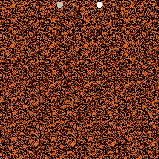
To get a 3D effect we need to modify our algorithm. We need to read the Depth Image at pixel (x,y) to get a value from 0 to 255. We divide that by 255 to get a fractional value between 0 and 1. We then multiply that value by the “maximum offset amount”, which is a tuneable parameter (i set it to 20), to get an offset amount. This offset is how much we should move ahead in the pattern.
So, instead of Output Image pixel (x,y) using the Color Image pixel (x % ColorWidth, y % ColorHeight), we are calculating an offset from the Depth Image and using the Color Image pixel ((x + offset) % ColorWidth, y % ColorHeight).
Doing that, we aren’t quite there. Some 3D effects are starting to pop out, but it doesn’t look quite right.
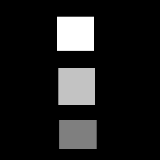
In fact, if you use the simpler depth map of the rectangles shown below, you can see the rectangles just fine, but there seems to be holes to the right of them.
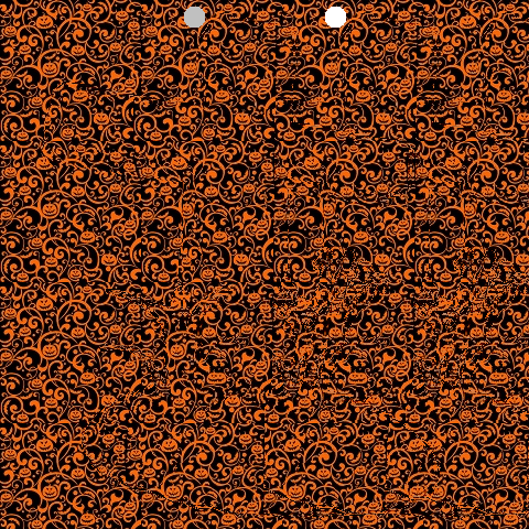
What we need to do is not just look into the Color Image at an offset location, but that we need to look at the Output Image we are building, at an offset location. Specifically, we need to look at it in the previous color tile repetition. We use the Output Image pixel at ((x + offset – ColorWidth), y).
A problem with that though, is that when x is less than ColorWidth, we’ll be looking at a pixel x value that is less than 0 aka out of bounds. When x < ColorWidth, we should use the Color Image pixel instead, using the same formula we had before ((x + offset) % ColorWidth, y % ColorHeight).
That fixes our problem with the simpler squares depth map. The holes to the right are gone.
And it also mostly fixes our “grave” image:
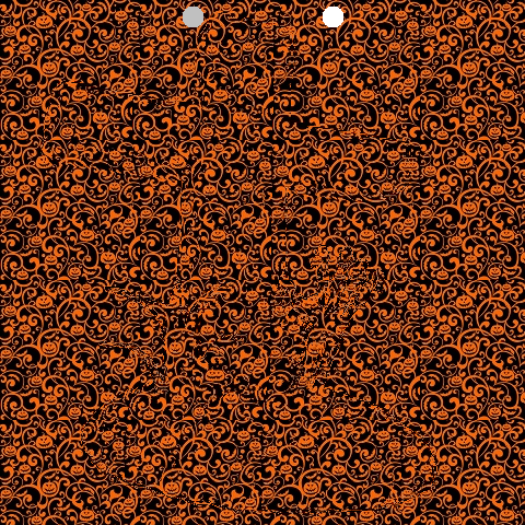
There is one problem remaining with the grave image though. How these images work is that your left eye needs to lined up with an unmodified tile on the left, and your right eye needs to be lined up with a modified tile on the right. The grave image has depth information very close to the left side, which makes that not be possible. To fix this, you can add an extra “empty color tile” on the left. That makes our image a little bit wider but it makes it work. This also has the added benefit of centering the depth map, where it previously was shifted to the left a bit.
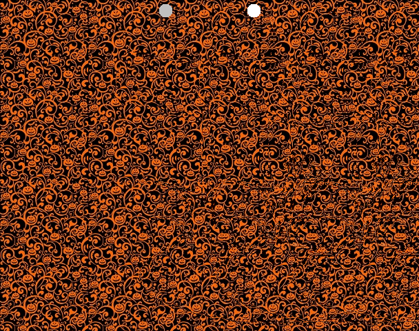
There we are, we are done!
Other Details
- I found it useful to normalize the greyscale depth map. Some of them don’t use the full 0 to 1 range, which means they aren’t making the most use of the depth available. Remapping them to 0 to 1 helps that.
- Some masks were meant to be binary black or white, but the images i downloaded form the internet had some grey in them (they were .jpg which is part of the problem – lossy compression). Having an option to binarize these masks was useful, forcing each pixel value or 0 or 1, whichever was closer.
- The binary masks i downloaded had the part i was interested in being black, with a white background. I made the code able to invert this, so the interest part would pop out instead of receeding in.
- The distance between the helper dots on the images are the width of the Color Image. A wider color image means a person has to work harder to get those dots to overlap, and it may not even be possible for some people (I’m unsure of details there hehe). I used tile sizes of 128.
- It’s hard to make out fine detail from the depth maps. It seems like larger, coarse features are the way to go, instead of fine details.
More Pictures
Here is the grave, with a different color texture. I find this one harder to see.
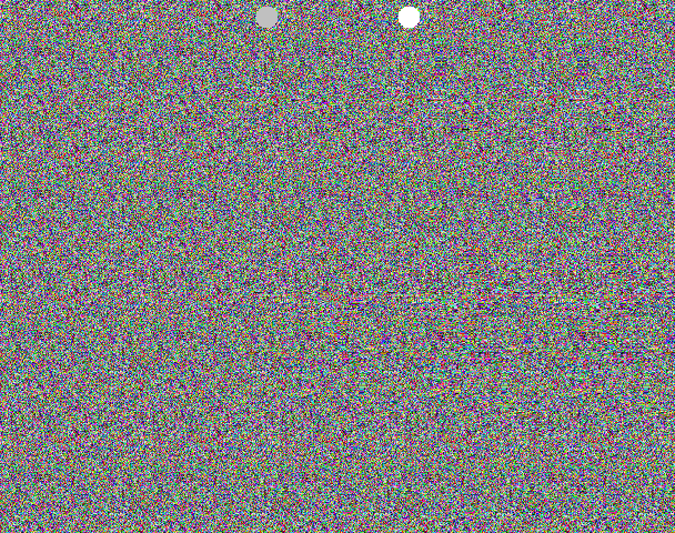
And another, using RGB white noise (random numbers). I can see this one pretty easily, but it isn’t as fun themed as the pumpkin image 🙂
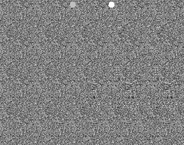
And here is greyscale white noise (random numbers) used for the color image. I can see this just fine too.
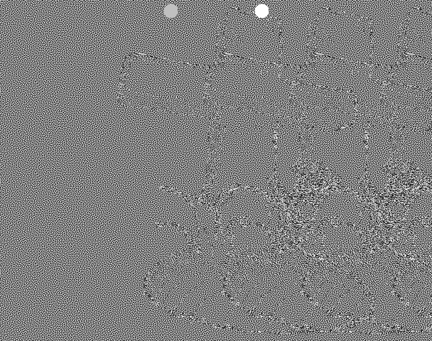
I also tried using blue noise as a Color Image but I can’t see the 3d at all, and it isn’t a mystery what the 3d image is. You can see the repetition of the depth map object from the feedback. I think it’s interesting that the repetition is needed to make it look right. I have no understanding of why that is, but if you do, please leave a comment!
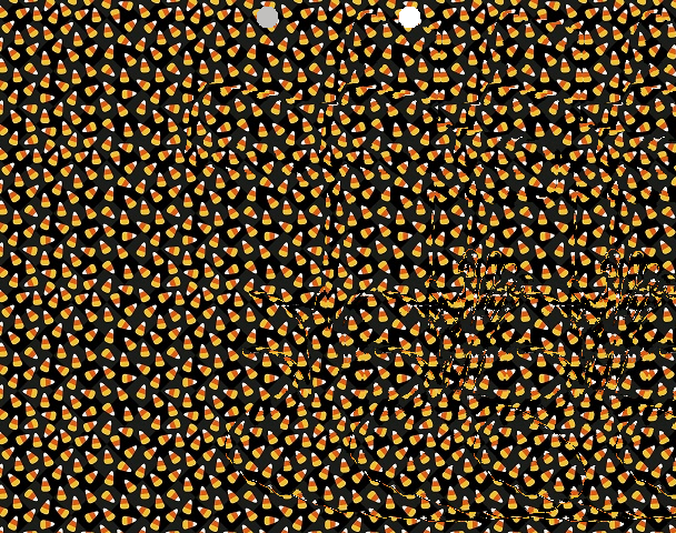
Here are some images that are not the grave. I find the pumpkin color texture works pretty nicely 🙂


Links
This video kicked off this nerd snipe: https://youtu.be/-okxLz1UauA?si=y_QK8-Bv4EzZSGBv
This was also helfpul: https://flothesof.github.io/making-stereograms-Python.html
Here is the code I wrote that makes these autostereograms again: https://github.com/Atrix256/Autostereogram
Lastly, I think it would be really neat to make a game that used this technique to render 3d. It could be something simple like a brick breaking game, or as complex as a first person shooter. A challenge with this is that you need to process the image from left to right, due to the feedback loop needed. That won’t be the fastest operation on the GPU, forcing it to serialize pixel processing unless anyone has any clever ideas to help that. Still, it would be pretty neat as a tech demo!

Very fun! Although, for me, I needed to invert all the depths (easy enough in code) to perceive that which should be near as near. Once I did this, the 3D shapes became much more obvious.
I believe this is corroborated by the math used in the revision of the source as of posting this:
Nearer things should have a larger separation. The depth offset scales linearly with depth map values that represent near pixels as 255 (normalized to 1), and then that depth offset is added to the position of the previous tile for sampling the line’s row so far… but that means nearer depth values cause sampling from closer to the current pixel being written rather than further from the current pixel being written, and hence near values adopt the perception of being far away since there is less separation instead of more.
I’m not sure how depth is quantized in the image — assuming it’s linear, then the separation for non-binarized cases could be improved by introducing a reciprocal?
Something I unfortunately only have time to idly wonder about is if there’s a way to minimize the permanent offsetting of the row. That might make the blue noise case better, although the blue noise is so hard to visually align at an arbitrary distance due to no easy nonuniform visual cues that it may not be sufficient even if the repeating pattern lines from the stereo separation from earlier in the row were eliminated.
A simple example of this kind of minimization might be choosing a global offset for each row such that the squared distance of the effective sampling offsets (after accounting for the recursive sampling nature) is minimized. More interesting would be if you can ‘fudge it’ a bit and let offsets drift enough to help globally reduce bleeding offsets on the right hand side of rows — I wonder if human perception even allows for this.
Does anyone know if any autostereogram methods account for this kind of global optimization already?
LikeLike
> Although, for me, I needed to invert all the depths
I can make it look both correct and inverted.
You can either make your focal point nearer than the screen (i.e. cross eyed) or equally distant farther than the screen.
For these, you want to focus farther away for the correct depth and nearer for the inverted depth.
Almost all stereograms I’ve seen use the farther focal point. I believe it’s less straining on your eyes.
LikeLike
OMG i got intregeded by this video too! to but you got farther! nice.
i made a playable tetris game using this a while ago. but cheated and used a library i found online
playable link
https://wisehackermonkey.github.io/magic-eye-tetris/
https://github.com/wisehackermonkey/magic-eye-tetris
here’s myunfinished p5.js sketch. didnt work. but a start
https://editor.p5js.org/wisemonkey/sketches/1JIkzBgNx
open questions:
is can smooth gradients be created using this method?
think dithering but fort autosteriograms
LikeLike
Great question about smooth gradient, hmm!
LikeLike
The 3d I perceive in these stereograms appears to be constructed of a stack of cutout pieces of paper at different depths, not smoothly varying depth. Have a look at the stepped 3d depth of the cross or the mount of soil underneath it, for example.
Perhaps the algorithm is only performing whole (not fractional) pixel shifts and this depth quantisation is a result? Not sure.
LikeLike
The 1994 DOS game Magic Carpet had an autostereogram mode
LikeLike
I was going to post the same thing – you might be able to play it at the internet archive: https://archive.org/details/msdos_Magic_Carpet_Plus_1995
LikeLike
The original Magic Carpet from 1994 had a stereogram mode 🙂
https://en.wikipedia.org/wiki/Magic_Carpet_(video_game)
LikeLike