
Posts in this series:
- Basic Camera, Diffuse, Emissive
- Image Improvement and Glossy Reflections
- Fresnel, Rough Refraction & Absorption, Orbit Camera
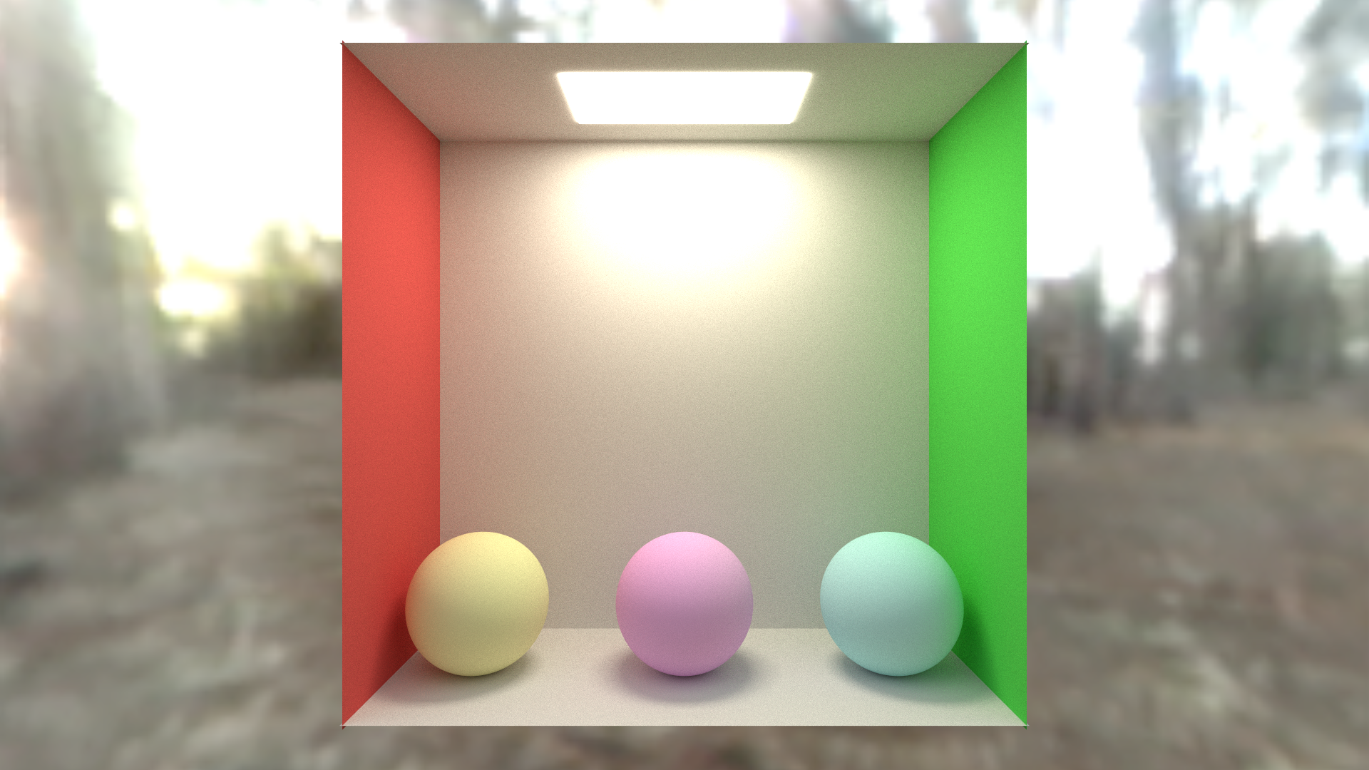
Below is a screenshot of the shadertoy that goes with this post. Click to view full size. That shadertoy can be found at:
https://www.shadertoy.com/view/WsBBR3
https://blog.demofox.org/wp-content/uploads/2020/06/pt2a_2.png
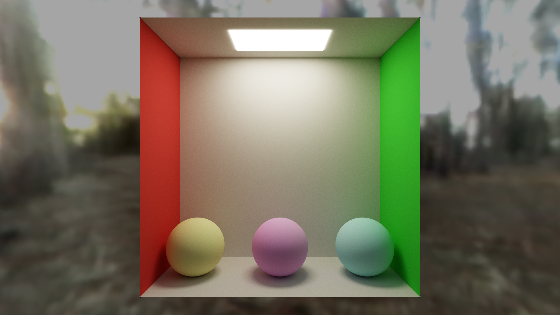
In this blog post we are going to improve the quality of our rendered image from last time, and also add specular / glossy reflections, to end up with the image above. Compare that to the image below, which is where we are starting from, after part 1.

On the menu today is…
- Anti Aliasing – This makes pixelated edges be smooth, which makes for a much better render
- sRGB – The space we do lighting calculations in are not the same as the display wants. This fixes that.
- Tone Mapping – This converts unbounded lighting to a displayable range.
- Exposure – This lets us brighten or darken our image before tone mapping, just like a camera’s exposure setting does.
- Glossy Reflections – We make some objects shiny
Anti Aliasing
Adding anti aliasing to a path tracer is super easy. All we need to do is add a random number between -0.5 and +0.5 to our pixel’s location, on the x and y axis.
Since the pixel color is the average over lots of frames, what this does is give us the “average color of the pixel”. That means if the edge of a shape goes through a pixel, the pixel will average the color of the shape, and also the color of whatever is in the background. That gives us smooth anti aliased edges.
To do this, find this code:
// calculate coordinates of the ray target on the imaginary pixel plane.
// -1 to +1 on x,y axis. 1 unit away on the z axis
vec3 rayTarget = vec3((fragCoord/iResolution.xy) * 2.0f - 1.0f, cameraDistance);
and replace it with this:
// calculate subpixel camera jitter for anti aliasing
vec2 jitter = vec2(RandomFloat01(rngState), RandomFloat01(rngState)) - 0.5f;

// calculate coordinates of the ray target on the imaginary pixel plane.
// -1 to +1 on x,y axis. 1 unit away on the z axis
vec3 rayTarget = vec3(((fragCoord+jitter)/iResolution.xy) * 2.0f - 1.0f, cameraDistance);
Doing that gives us this image below. You might want to click to view it full size and compare it vs last image, to see how the edges of the spheres are smooth now. Viewing the smaller image hides the pixelation.

sRGB
The colors that we send to a display are not the same as the colors that we see. This is because human vision is not linear.
With only 256 shades of color in 8 bit per color channel images, if we split the shades evenly, we’d find that there wasn’t enough dark shades because our eyes can see more detail in darker shades.
To make up for this, sRGB was made, which makes it so the values between 0 and 255 are not linearly spaced – there are more values in darker colors and less in the lighter colors.
If we do our lighting calculations in sRGB though, the math doesn’t work right because there was a non linear transform applied to our color channels.
To fix this, whenever we read a color from a texture, we should convert from sRGB to linear. Also, whenever we write out a pixel, we want to convert from linear to sRGB so it shows up correctly on the display.
We need to add these functions to our shadertoy. Make a new “common” tab and put it in there. The common tab is a header included by all other tabs, so things we put there are usable by all other tabs. In the shader that goes with this post, i put many utility functions, constants, and user controllable parameters in the common tab.
vec3 LessThan(vec3 f, float value)
{
    return vec3(
        (f.x < value) ? 1.0f : 0.0f,
        (f.y < value) ? 1.0f : 0.0f,
        (f.z < value) ? 1.0f : 0.0f);
}

vec3 LinearToSRGB(vec3 rgb)
{
    rgb = clamp(rgb, 0.0f, 1.0f);

    return mix(
        pow(rgb, vec3(1.0f / 2.4f)) * 1.055f - 0.055f,
        rgb * 12.92f,
        LessThan(rgb, 0.0031308f)
    );
}

vec3 SRGBToLinear(vec3 rgb)
{
    rgb = clamp(rgb, 0.0f, 1.0f);

    return mix(
        pow(((rgb + 0.055f) / 1.055f), vec3(2.4f)),
        rgb / 12.92f,
        LessThan(rgb, 0.04045f)
	);
}
ERRATA SRGBToLinear() just returned the input, in the original version of this post. That was incorrect, and correcting that changes the results you get from here on out. The only thing using the function was the skybox lookup, but that means you will get different results than are shown in the screenshots here. The problem isn’t on your end, it’s mine. Sorry about that! In fact, instead of skybox lighting being too bright as i talk about later on and having to multiply it by 0.5, it ends up being too dim and in the final shader you’ll see i multiply it by 2. Apologies and thank you for reading 🙂
There are two places we need to use this functionality. The first place is where we read the cube map when rays miss the scene geometry.
Find this code:
// if the ray missed, we are done
if (hitInfo.dist == c_superFar)
{
    ret += texture(iChannel1, rayDir).rgb * throughput;
    break;
}
Change it to this:
// if the ray missed, we are done
if (hitInfo.dist == c_superFar)
{
    ret += SRGBToLinear(texture(iChannel1, rayDir).rgb) * throughput;
    break;
}
The other place we want to change is where we write the final pixel color out.
In the “Image” tab, find this code:
vec3 color = texture(iChannel0, fragCoord / iResolution.xy).rgb;
and replace it with this:
vec3 color = texture(iChannel0, fragCoord / iResolution.xy).rgb;

// convert from linear to sRGB for display
color = LinearToSRGB(color);
Doing that, we get this image:
https://blog.demofox.org/wp-content/uploads/2020/06/pt2c.png
You might notice the balls changed color significantly. That’s because they were sRGB colors before but now they are linear colors. We can adjust their colors to make them look better though. If we change the 0.75s if their albedo to 0.5s, that gives us an image like this:
Tone Mapping & Exposure
The next thing to tackle is the fact that when we are calculating lighting, the range of light goes from 0 (perfect black) up to an unbounded amount of brightness, but our display can only display values between 0 and 1.
Tone mapping is the process of remapping the values to the 0 to 1 range. Tone mapping preserves detail in the darks while also making pixels that are too bright also have recognizable detail. We are going to use a luminance only fit of the ACES tone mapper. This tone mapping code was made by Krzysztof Narkowicz and you can read more about it on his website: https://knarkowicz.wordpress.com/2016/01/06/aces-filmic-tone-mapping-curve/
Here is the function to put in the common tab:
// ACES tone mapping curve fit to go from HDR to LDR
//https://knarkowicz.wordpress.com/2016/01/06/aces-filmic-tone-mapping-curve/
vec3 ACESFilm(vec3 x)
{
    float a = 2.51f;
    float b = 0.03f;
    float c = 2.43f;
    float d = 0.59f;
    float e = 0.14f;
    return clamp((x*(a*x + b)) / (x*(c*x + d) + e), 0.0f, 1.0f);
}
That function takes linear color in and gives linear color out, so we need to call it after we get the raw color, but before we convert that color to sRGB, in the image tab.
    vec3 color = texture(iChannel0, fragCoord / iResolution.xy).rgb;

    // convert unbounded HDR color range to SDR color range
    color = ACESFilm(color);

    // convert from linear to sRGB for display
    color = LinearToSRGB(color);

    fragColor = vec4(color, 1.0f);
Doing that we get this image.

The lighting on the back wall has mellowed out a bit and looks a lot more natural which is nice. It still seems a bit bright though.
To fix this we are going to do 2 things. Firstly, we are going to multiply the value we read from the skybox by 0.5 to darken the sky box a little. (i won’t paste code for that, just multiply the texture value by 0.5 after converting it to linear)
Secondly, we are going to apply EXPOSURE to the scene, by multiplying the color by a value of 0.5 before we put it through the tone mapper. That makes it so the entirety of the code in the “Image” tab is this:
void mainImage( out vec4 fragColor, in vec2 fragCoord )
{
    vec3 color = texture(iChannel0, fragCoord / iResolution.xy).rgb;

    // apply exposure (how long the shutter is open)
    color *= c_exposure;

    // convert unbounded HDR color range to SDR color range
    color = ACESFilm(color);

    // convert from linear to sRGB for display
    color = LinearToSRGB(color);

    fragColor = vec4(color, 1.0f);
}
With those two changes, our render now looks like this:
Glossy Reflections
Now for the part that everyone is waiting for: glossy reflections to make shiny things!
If you’ve done simple lighting in shaders before, you’ve probably used reflect() to calculate a light reflection ray to do some specular highlights (shiny spots) on objects.
We are going to put albedo and emissive into a SMaterialInfo struct inside of SRayHitInfo, and we are also going to add these fields:
- percentSpecular – A float between 0 and 1. What percentage of the light that hits this object is going to be reflected specularly instead of diffusely. This is the percentage chance that a ray hitting this surface is going to choose a specular reflection instead of a diffuse one
- roughness – A float between 0 and 1. How rough the surface is, which controls how blurry the reflection is. A value of 0 is a very sharp clean mirror like reflection, and a value of 1 is so blurry it looks just like diffuse.
- specularColor – A vec3 which is the color of specular reflections, just like how albedo is the color of diffuse reflections. This lets you have different colors for diffuse and specular reflections, letting you have colored metal and similar.
Here is how our shading is going to work:
- We are going to roll a random number from 0 to 1. If it’s less than percentSpecular, we are doing a specular ray, else we are doing a diffuse ray.
- Diffuse rays use cosine weighted random hemisphere samples like before.
- A fully rough specular ray is going to use that diffuse ray direction.
- A zero roughness specular ray is going to use a ray direction calculated from reflect().
- A specular ray with roughness between 0 and 1 is going to square the roughness (personal preference, you don’t have to square it), and use that value to linearly interpolate between the specular and diffuse ray directions, normalizing the result.
- Instead of always multiplying throughput by albedo, if it’s a specular ray, we are going to instead multiply it by specularColor
That is all there is to it! Find this code:
// update the ray position
rayPos = (rayPos + rayDir * hitInfo.dist) + hitInfo.normal * c_rayPosNormalNudge;

// calculate new ray direction, in a cosine weighted hemisphere oriented at normal
rayDir = normalize(hitInfo.normal + RandomUnitVector(rngState));

// add in emissive lighting
ret += hitInfo.emissive * throughput;

// update the colorMultiplier
throughput *= hitInfo.albedo;
And replace it with this:
// update the ray position
rayPos = (rayPos + rayDir * hitInfo.dist) + hitInfo.normal * c_rayPosNormalNudge;

// calculate whether we are going to do a diffuse or specular reflection ray
float doSpecular = (RandomFloat01(rngState) < hitInfo.material.percentSpecular) ? 1.0f : 0.0f;

// Calculate a new ray direction.
// Diffuse uses a normal oriented cosine weighted hemisphere sample.
// Perfectly smooth specular uses the reflection ray.
// Rough (glossy) specular lerps from the smooth specular to the rough diffuse by the material roughness squared
// Squaring the roughness is just a convention to make roughness feel more linear perceptually.
vec3 diffuseRayDir = normalize(hitInfo.normal + RandomUnitVector(rngState));
vec3 specularRayDir = reflect(rayDir, hitInfo.normal);
specularRayDir = normalize(mix(specularRayDir, diffuseRayDir, hitInfo.material.roughness * hitInfo.material.roughness));
rayDir = mix(diffuseRayDir, specularRayDir, doSpecular);

// add in emissive lighting
ret += hitInfo.material.emissive * throughput;

// update the colorMultiplier
throughput *= mix(hitInfo.material.albedo, hitInfo.material.specularColor, doSpecular);
If we update our scene geometry and materials a bit, we now can get the final image:

The green balls in the back have a percentSpecular of 1.0, so they are all specular. Their roughness from left to right is: 0, 0.25, 0.5, 0.75, 1.0. Their specular color is (0.3, 1.0, 0.3) which makes them have a green tint. In PBR speak, this would be a green metal (we aren’t using PBR specular calculations though!).
The yellow ball in the front left has a percent specular of 0.1, a roughness of 0.2 and a specular color of (0.9f, 0.9f, 0.9f). In PBR speak, this is a dielectric.
The pinkish ball in the front center has the same except a percent specular of 0.3, so is shinnier. (Still a dielectric)
The blue and magenta ball in the front right is there to show that if you pick bad material values, you can get something that doesn’t look very good. That ball has an albedo of pure blue, a percent specular of 0.5, a roughness of 0.5 and a specular color of pure red. That isn’t a very realistic thing you could see in the real world – a blue object with red reflections – so it doesn’t look very good in the render. Garbage in, garbage out. In PBR speak, you could get this by having a dual layer material… a blue very rough or diffuse dielectric, with a clear coat that acts like a metal? It doesn’t make much sense in PBR which further shows that it isn’t a very well motivated material, which is why it doesn’t look very good.
If you feel like taking things a little further, our render could look better with fresnel, making glancing ray angles be more reflective. I’m not planning on doing that in this series but I do have a blog post on it here: https://blog.demofox.org/2017/01/09/raytracing-reflection-refraction-fresnel-total-internal-reflection-and-beers-law/
Update 3/1/24: Since writing this post, I’ve heard that perturbing (randomizing) the normal instead of the ray direction is closer to how PBR specular actually works and should give better results. I haven’t tried it, but it makes when you think about it. It’s the surface that is bumpy, causing reflections to scatter in different directions at the micro/meso scale.
Bonus 1: Russian Roulette
Each ray will bounce up to 8 times, but there are times when it really doesn’t need 8 bounces to give the right look.
If we were somehow able to detect this, we could end a ray early, especially if we knew how to handle the probabilities correctly to not add bias from ending early.
Russian roulette is a method for doing just that.
We are going to find the maximum color channel value in our throughput, R, G or B, and that value will be the percentage chance that we keep going with our ray after each bounce. When we do keep going, we are going to divide our throughput by that chance of keeping the ray, which makes up for the fact that we kill some of the rays there some of the other times, by making future bounces brighter.
What this means is that as the throughput gets lower, meaning future ray bounces are likely to impact the final image less, we become more likely to stop the ray bouncing around early.
This is mainly just a performance optimization, but is good because it lets you converge faster due to being able to get more samples more quickly.
Just put this code right under where we update the throughput by multiplying it by diffuse or specular.
// Russian Roulette
// As the throughput gets smaller, the ray is more likely to get terminated early.
// Survivors have their value boosted to make up for fewer samples being in the average.
{
float p = max(throughput.r, max(throughput.g, throughput.b));
if (RandomFloat01(rngState) &gt; p)
break;
// Add the energy we 'lose' by randomly terminating paths
throughput *= 1.0f / p;
}
To give an idea of how this affects performance, on my machine at (i forget) resolution and (i forget) renders per frame, i was getting 30 fps which is 33.3 milliseconds per frame. After I put in this Russian roulette code, it went up to 40 fps which is 25 milliseconds per frame. Same exact visual results, but 8ms less render time per frame, or a 25% improvement in speed.
Bonus 2: Space Bar to Reset
It can be hard to get a full screen screenshot in shadertoy, because you have to click the button to make it full screen (see image below) and then it already has some of the small rendering still there on the screen.
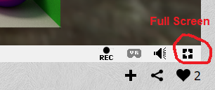
We can actually make it so when you press the space bar, that it resets the render.
How you do this is instead of using iFrame to figure out how much to blend this frame into the next, you store the blend (1/framesRendered) in the alpha channel of each pixel. You can then assign the keyboard as a texture to iChannel2 (it’s under the Misc tab) and then read that “keyboard texture” to see if the space key was pressed.
Find this code:
// average the frames together
vec3 lastFrameColor = texture(iChannel0, fragCoord / iResolution.xy).rgb;
color = mix(lastFrameColor, color, 1.0f / float(iFrame+1));

// show the result
fragColor = vec4(color, 1.0f);
And replace it with this (after assigning the keyboard as a texture in the iChannel2 slot!):
// see if space was pressed. if so we want to restart our render.
// This is useful for when we go fullscreen for a bigger image.
bool spacePressed = (texture(iChannel2, vec2(32.5/256.0,0.25)).x &gt; 0.1);
// average the frames together
vec4 lastFrameColor = texture(iChannel0, fragCoord / iResolution.xy);
float blend = (lastFrameColor.a == 0.0f || spacePressed) ? 1.0f : 1.0f / (1.0f + (1.0f / lastFrameColor.a));
color = mix(lastFrameColor.rgb, color, blend);
// show the result
fragColor = vec4(color, blend);
Now, you can flip to full screen and press space bar to reset the render to get a better larger render.
Closing
Don’t forget… if you are trying to make a render and you are seeing 60fps, that means you probably could be converging faster and you are waiting for no good reason. Try turning c_numRendersPerFrame up until you aren’t at 60fps anymore. Anything lower than 60 means it’s working near capacity, getting it down to 10 or 5 or lower fps isn’t going to help you, so don’t worry about bringing your shadertoy tab to a crawl, it doesn’t do any good.
Be on the lookout for the next post in this series. We have some more topics to casually implement, including: depth of field and bokeh, camera movement, participating media (fog), bloom, refraction & transparencies, and more.
Thanks for reading and share any cool things you make with me on twitter at @Atrix256
